I would respectfully repeat my question - is it better to use one common power transformer (with separate secondary windings) or two independent power transformers? Would two separate transformers reflect in change of this measurement?
http://theaudiocritic.com/cwo_images/image122.jpg
Pavel,
There is no issue here. If you have one large transformer then if one channel has a peak power demand when the other doesn't more power is available to that channel.
However as long as you are actually listening to music and not studio effects that will not happen. So the increase in channel separation will be more important than the possible increase in dynamic headroom.
There is a second major advantage. If you wire the secondaries on each transformer with opposite connections then the channel post surge rebound will be faster. There will also be some EMI cancellation. There is one major pro audio manufacturer who wires the primaries out of phase for this reason. It does give a measurable difference in peak power.
Now interestingly enough that phase boost is actually more than the extra float voltage from a single transformer on the set I measured! My big transformers all have better than 5% regulation from minimum actual load to rated load. (Big being over 250 VA.) I expected the phase boost to be about 1% but it seems to be closer to 10%!
Another less obvious advantage is that with two transformers you can spread out the weight and make it an easier to carry unit.
But then you wanted Johns opinion, so just ignore this.
ES
Not so odd. I worked at a place that used a similar output scheme with a uA709 for input. Many lasted for years under heavy use. The ones that blew usually did so at turn on (not long into their lifetime)Oddly enough, I ran 8 units absolutely full bore plus for several years 6 nights a week, 6 hours per night. Never had one blow anything internal whatsoever. R14 opened on one unit, it was undersized for the dissipation. I do admit however, I threw out the cases and heatsinks that came with the kits, installed chimneys with 5 inch fans.
PMA...how did you layout the supply rails for the outputs, and how did you arrange the grounding star? I'm very interested in the input pair grounding scheme, both from the input and from the feedback.
jn
Getting back to the problem mentioned last night about 'significant distortion' coming from the input stage:
The very first Parasound amp, the HCA2200MK1, that I had any input on, used a dual IC at the very input to make an easy changeover from single ended input to balanced input. It looked pretty good on paper. I decided to keep it, initially, and only selected the IC that it used. I selected the AD712, because it met all of the criteria that I thought was necessary, and it appeared to be the best device that I could find at the time that FIT into the LF353 pin-out that the Taiwanese had fabricated. I didn't want to 'rock any boats' in my first venture with Parasound, and use a different op amp layout, such as 2 single op amps, that was made by a competitor (PMI) (later absorbed into ADI), which was also an interesting choice.
I thought it was a pretty good solution for an amp in its price range, and I fully hoped for a 'B' rating from Stereophile.
I didn't LISTEN to the amp directly, before it went to review, I just measured it, confident that the measurements would show up anything that could be wrong.
Well, it failed to impress the Stereophile reviewers, no matter how well it measured, and I got in a lot of trouble with my boss for not getting some subjective input on it, before it got reviewed. In any case, I had to make it work, somehow, or at least know why it failed to deliver. (that is the next step in this saga)
But then you wanted Johns opinion, so just ignore this.
ES
Don't be that modest, Ed
") . And thanks for your comment. I prefer two transformers, as you probably might have guessed.
. And thanks for your comment. I prefer two transformers, as you probably might have guessed.Back to classroom benches.
Last edited:
Ah, fair enough.I don't know what Stereophile does when it measures crosstalk.
My concern is that the test needs to be done in situ and using accurate loads in order to be useful. Using test equipment on the bench only tells what happens on the bench.
A two channel device needs to be connected to a two channel source, and without line cord ground disconnected.
jn
Don't be that modest, Ed
Back to classroom benches.
What about SMPS? I bought a couple +-60V 800W ones just to see for myself. I was going to try separate box maybe double with some NOS high current feedthrough caps.
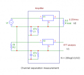
Why not? You only must not send any crosstalk (from preamp or soundcard) to the measured channel. I measure with left and right ground connected together, one channel is driven from generator and loaded by whatever load (does not make much difference), second channel provided with cable and cable input shorted with resistor equal to preamp output impedance.
Everything depends on how your amplifier is wired in the box and if you have completely separated power supplies or not. Power supply (transformer) is the coupling point.
Everything depends on how your amplifier is wired in the box and if you have completely separated power supplies or not. Power supply (transformer) is the coupling point.
What about SMPS?
I have never tried it in a serious (linear) amplifier project, though I have many in measurement + control applications.
OK, here is where I sat, 20 years ago. I was in trouble with my new boss for making a 'failed product', and I had to do something useful to make the circuit work properly.
The first thing that I knew that was different from any previous successful design that I had made for other manufacturers was: The addition of an IC at the input. So, almost in desperation, I had to find a way to remove the IC from the input, and put a discrete circuit in its place.
The easiest way was to just remove the IC for unbalanced input, and drive the feedback resistor as well as the input, when doing a balanced input drive. Since most of the inputs back then were single ended, this was just an 'addition' or feature, but I realized that I HAD to buffer the feedback input to get the input impedances to match, so I selected a class A, open loop jfet follower. This looked OK on paper, BUT it was a significant challenge for the open loop follower to drive the 1800 ohms or so that was necessary. So, I selected the highest current part easily available at the time, the Toshiba 2SK170V, the highest current selection of that device, so that I would have enough peak current to keep in Class A, and also have the lowest possible output impedance without negative feedback from a jfet. Unfortunately, I had to bias these parts away from Idss for temperature and a more ideal operating range, so I had to select a pair of bias/local feedback resistors, and I first chose 47 ohms.
Now, lab measurements of this design worked well enough, and I included it into the updated 2200 design, however when it went into production, the Taiwanese ignored the 'V' spec and used either 'bl' or 'gr' and we got into trouble. Not only did these lower current parts not have the current drive necessary, but the Taiwanese KEPT THE 47 OHM RESISTOR, when it should have been changed to 10 ohms or so, corresponding to the LOWER Idss jfet that they elected to use (because it was cheaper they said) so the follower was compromised.
I missed this in final evaluation, because I did not have a balanced drive on my test analyzer at the time. However, it did NOT escape the evaluation of 'The Audio Critic' and I found out about the problem and fixed it. However, I took a lot a 'flack' from the magazine for it, although I appreciated that they found the problem, so that it could be fixed.
They could not conceive WHY a designer might REMOVE an IC from an otherwise all discrete audio design, and they berated me for it.
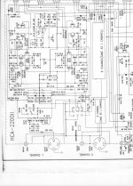
In any case, the HCA2200Mk2 came out a 'winner' with a solid 'B' rating, exactly what I hoped to achieve from the product. Here again is the MK2 input schematic with the 47 ohm resistors:
The first thing that I knew that was different from any previous successful design that I had made for other manufacturers was: The addition of an IC at the input. So, almost in desperation, I had to find a way to remove the IC from the input, and put a discrete circuit in its place.
The easiest way was to just remove the IC for unbalanced input, and drive the feedback resistor as well as the input, when doing a balanced input drive. Since most of the inputs back then were single ended, this was just an 'addition' or feature, but I realized that I HAD to buffer the feedback input to get the input impedances to match, so I selected a class A, open loop jfet follower. This looked OK on paper, BUT it was a significant challenge for the open loop follower to drive the 1800 ohms or so that was necessary. So, I selected the highest current part easily available at the time, the Toshiba 2SK170V, the highest current selection of that device, so that I would have enough peak current to keep in Class A, and also have the lowest possible output impedance without negative feedback from a jfet. Unfortunately, I had to bias these parts away from Idss for temperature and a more ideal operating range, so I had to select a pair of bias/local feedback resistors, and I first chose 47 ohms.
Now, lab measurements of this design worked well enough, and I included it into the updated 2200 design, however when it went into production, the Taiwanese ignored the 'V' spec and used either 'bl' or 'gr' and we got into trouble. Not only did these lower current parts not have the current drive necessary, but the Taiwanese KEPT THE 47 OHM RESISTOR, when it should have been changed to 10 ohms or so, corresponding to the LOWER Idss jfet that they elected to use (because it was cheaper they said) so the follower was compromised.
I missed this in final evaluation, because I did not have a balanced drive on my test analyzer at the time. However, it did NOT escape the evaluation of 'The Audio Critic' and I found out about the problem and fixed it. However, I took a lot a 'flack' from the magazine for it, although I appreciated that they found the problem, so that it could be fixed.
They could not conceive WHY a designer might REMOVE an IC from an otherwise all discrete audio design, and they berated me for it.
In any case, the HCA2200Mk2 came out a 'winner' with a solid 'B' rating, exactly what I hoped to achieve from the product. Here again is the MK2 input schematic with the 47 ohm resistors:
Attachments
Pavel,
There is no issue here. If you have one large transformer then if one channel has a peak power demand when the other doesn't more power is available to that channel.
However as long as you are actually listening to music and not studio effects that will not happen. So the increase in channel separation will be more important than the possible increase in dynamic headroom.
There is a second major advantage. If you wire the secondaries on each transformer with opposite connections then the channel post surge rebound will be faster. There will also be some EMI cancellation. There is one major pro audio manufacturer who wires the primaries out of phase for this reason. It does give a measurable difference in peak power.
Now interestingly enough that phase boost is actually more than the extra float voltage from a single transformer on the set I measured! My big transformers all have better than 5% regulation from minimum actual load to rated load. (Big being over 250 VA.) I expected the phase boost to be about 1% but it seems to be closer to 10%!
Another less obvious advantage is that with two transformers you can spread out the weight and make it an easier to carry unit.
But then you wanted Johns opinion, so just ignore this.
ES
I'm listening , Thanks , but then you directed your answer to Pavel, so just ignore this ..
Why not? You only must not send any crosstalk (from preamp or soundcard) to the measured channel. I measure with left and right ground connected together, one channel is driven from generator and loaded by whatever load (does not make much difference), second channel provided with cable and cable input shorted with resistor equal to preamp output impedance.
Everything depends on how your amplifier is wired in the box and if you have completely separated power supplies or not. Power supply (transformer) is the coupling point.
Seperate power cords and switch necessary .... ?
Why not? You only must not send any crosstalk (from preamp or soundcard) to the measured channel. I measure with left and right ground connected together, one channel is driven from generator and loaded by whatever load (does not make much difference), second channel provided with cable and cable input shorted with resistor equal to preamp output impedance.
Everything depends on how your amplifier is wired in the box and if you have completely separated power supplies or not. Power supply (transformer) is the coupling point.
The star ground can be a coupling point. Or, more precisely, the wiring to that star ground.
To accurately measure crosstalk, it is important to exercise the entire system the amplifier is within. This does include the source connections.
For unbalanced inputs, remember that at low frequency both input cables share a common signal return path, and it is not the input cable shields, it is the power cordage ground. At higher audio frequencies, the input cables share return path 50/50. At very high frequencies, each input cable gets it's own return path, it's shield.
Internally, the supply rails to the output stages need the return current co-mingling to reduce internal couplings. How many designers twist the output wires such that the output ground wire goes back to the pass devices, and then twists around both supply rails back to the supply caps?
jn
Seperate power cords and switch necessary .... ?
No.
The star ground can be a coupling point. Or, more precisely, the wiring to that star ground.
jn
I have nothing like that. I have two completely independent amplifiers in one case. To me, star ground is a wrong solution.
Last edited:
I have nothing like that. I have two completely independent amplifiers in one case. To me, star ground is a wrong solution.
How do you couple rail to output return currents to prevent solenoidal fields?
Are you using balanced inputs? edit: I see you are, but individually shield each wire..you've a loop at the inputs.
I agree with you that star grounds are incorrect for low impedance circuits.
jn
Last edited:
Yes, only Zobel. My SR = 120V/us. Inductance of wires from pcb board to rear panel terminals, about 0.2 - 0.5 uH, is enough.
How did you measure the inductance of a wire? Do you mean the complete loop?
jn
Some of you might ask: Why a 'B' rating, why not an 'A' rating? This comes down to the issues mentioned by PMA, i.e. Layout, heatsink area, and parts quality.
An up-to-date topology such as used by Parasound is only part of the equation. Done without significant mistakes, it can achieve a 'subjective' 'B' rating, but rarely an 'A' rating.
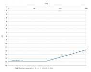
The next most important factor is LAYOUT. I have always had trouble with Parasound over this, until we launched the JC series. It was just outside of my control for about 10 years. As shown in the crosstalk specs, the problem can be measured. Other problems may be more subtle, YET just as 'subjectively' problematic, and without measured PROOF, it is hard to convince someone in Taiwan whom I have never met, thousands of miles away, that these problems are equally important, without measurements showing it.
Things came to a 'boiling point' with Parasound and me about 15 years ago, when Bob Crump, Carl Thompsen, and I were designing the CTC Blowtorch preamp in the USA, and Taiwan was even ignoring some of my original design advice, and our product ratings dropped off the chart.
At this time, my associate Bob Crump and I decided to tackle the Parasound problems ourselves, for our own use. It was relatively easy for me to acquire Parasound amps, but they were then insufficient to be used effectively with the CTC Blowtorch preamp.
Bob, at the time, used a very expensive discrete amp made by 'Bear' who contributes to this website. So when we went to CES, we brought 'Bear's' amp to show off the CTC Blowtorch, rather than Parasound. In fact, nobody of my professional acquaintance would use the Parasound amps at that time. I measured and measured, but I found little out of line.
I donated an HCA3500 power amp that had failed with Brian Cheney (he would not even take it to CES as a back-up amp) to see what we could do with it. Bob REMOVED dozens of parts, phased the transformers properly, exchanged diodes for hi speed ones, replaced bypass caps, and feedback resistors, etc. etc. THEN we had a good listening product, and the next year we took it to the CES to play with the CTC Blowtorch. It was a success, so much so, that we decided to buy Parasound amps at cost and modify them, ourselves, for sale at a modest profit. We did this for a couple of years, but it just was too much work, so we considered stopping. Then Parasound came to realize that maybe our upgrades, and even more (like better layout) would make some Parasound amps venture into 'A' territory, and the JC-1 was designed and built, then the JC-2, 3, following our mods that we knew worked, yet we could not easily measure the differences. And that is where we are today.
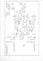
Interestingly, we did NOT change the basic schematic much, just attention to details. (JC-1 example to compare to earlier designs)
An up-to-date topology such as used by Parasound is only part of the equation. Done without significant mistakes, it can achieve a 'subjective' 'B' rating, but rarely an 'A' rating.
The next most important factor is LAYOUT. I have always had trouble with Parasound over this, until we launched the JC series. It was just outside of my control for about 10 years. As shown in the crosstalk specs, the problem can be measured. Other problems may be more subtle, YET just as 'subjectively' problematic, and without measured PROOF, it is hard to convince someone in Taiwan whom I have never met, thousands of miles away, that these problems are equally important, without measurements showing it.
Things came to a 'boiling point' with Parasound and me about 15 years ago, when Bob Crump, Carl Thompsen, and I were designing the CTC Blowtorch preamp in the USA, and Taiwan was even ignoring some of my original design advice, and our product ratings dropped off the chart.
At this time, my associate Bob Crump and I decided to tackle the Parasound problems ourselves, for our own use. It was relatively easy for me to acquire Parasound amps, but they were then insufficient to be used effectively with the CTC Blowtorch preamp.
Bob, at the time, used a very expensive discrete amp made by 'Bear' who contributes to this website. So when we went to CES, we brought 'Bear's' amp to show off the CTC Blowtorch, rather than Parasound. In fact, nobody of my professional acquaintance would use the Parasound amps at that time. I measured and measured, but I found little out of line.
I donated an HCA3500 power amp that had failed with Brian Cheney (he would not even take it to CES as a back-up amp) to see what we could do with it. Bob REMOVED dozens of parts, phased the transformers properly, exchanged diodes for hi speed ones, replaced bypass caps, and feedback resistors, etc. etc. THEN we had a good listening product, and the next year we took it to the CES to play with the CTC Blowtorch. It was a success, so much so, that we decided to buy Parasound amps at cost and modify them, ourselves, for sale at a modest profit. We did this for a couple of years, but it just was too much work, so we considered stopping. Then Parasound came to realize that maybe our upgrades, and even more (like better layout) would make some Parasound amps venture into 'A' territory, and the JC-1 was designed and built, then the JC-2, 3, following our mods that we knew worked, yet we could not easily measure the differences. And that is where we are today.
Interestingly, we did NOT change the basic schematic much, just attention to details. (JC-1 example to compare to earlier designs)
Attachments
I have nothing like that. I have two completely independent amplifiers in one case. To me, star ground is a wrong solution.
I had thought the same , in some designs it's unavoidable thou ..
@JC,
Very interesting John, I have heard Bear's amplifier, it's a good product, were the updates /Mod's confined to just the HCA3500...?
How do you couple rail to output return currents to prevent solenoidal fields?
Are you using balanced inputs? edit: I see you are, but individually shield each wire..you've a loop at the inputs.
I agree with you that star grounds are incorrect for low impedance circuits.
jn
JN, you are quite curious
The prototype measured has only unbalanced inputs. It was measured the same way as when it is used for playback, pls see attached image. Regarding internal wiring - that's something I do not want to speak about in detail.
Attachments
- Status
- Not open for further replies.
- Home
- Member Areas
- The Lounge
- John Curl's Blowtorch preamplifier part II