
")
What complaints were those, SY?
Issue 20. P42. "Substandard distortion performance as a result of some kludgy circuit design..." I think this was in reaction to a chimp review in Stereophile. TAC did note that the distortion was still low enough to be inaudible. The A21 got a somewhat more positive review: "...while it doesn’t set world records in any of the various measurement categories, proves to be a thoroughly clean amplifier on the lab bench."
Actually SY, I believe that you are talking about a colleague of yours finding an oversight in the implementation of a particular design that I corrected immediately, once I knew about it. The A21 had no such problem.
Of course, I was not told about the problem until I was chastised in print, and I was not offered any rebuttal. I decided that this reviewer, although well educated (PhD) was not worth knowing further, on a social basis, and I have politely rebutted his casual conversation with me now more than 10 years now, even when he attempted to do so, once, at a CES. It is not fair to be judged without a fair trial.
Of course, I was not told about the problem until I was chastised in print, and I was not offered any rebuttal. I decided that this reviewer, although well educated (PhD) was not worth knowing further, on a social basis, and I have politely rebutted his casual conversation with me now more than 10 years now, even when he attempted to do so, once, at a CES. It is not fair to be judged without a fair trial.
Last edited:
Actually SY, I believe that you are talking about a colleague of yours...
Not that I'm aware of. The root cause of the downgrade in performance between the 2200 and the 2200 II was a Stereophile "reviewer" whom I've never met. You're just trying to satisfy your niche market, which is perfectly understandable, even if the performance is degraded.
It was David A. Rich, Ph.D. who wrote a criticism of my removing the AD712, and using a discrete replacement consisting of a pair of 2SK170 fets per channel instead. He was right, IC's measure better! However, what he ACTUALLY measured was a design change made in Taiwan without my knowledge. We sorted this out internally, when I showed written evidence of their mistake that caused excessive 2'nd harmonic distortion from the jfets.
What happened is that I specified a V part, 10ma-20ma, and they used a GR part 3-6ma. NOT GOOD, when the bias resistors that I designed in were for the V part. The resistors starved off the GR parts and distortion was added. Of course, I was not informed by Parasound or the magazine until the review was published, and I was not asked to comment on it.
What happened is that I specified a V part, 10ma-20ma, and they used a GR part 3-6ma. NOT GOOD, when the bias resistors that I designed in were for the V part. The resistors starved off the GR parts and distortion was added. Of course, I was not informed by Parasound or the magazine until the review was published, and I was not asked to comment on it.
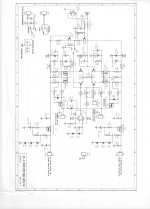
Neat and groovy !Now, WHY would we want an 'improved' power supply buffer. The most important reason would be when we want the very HIGHEST output swing from the amplifier for the existing output transistors used. Even if we use the 'best' output transistors, we run into 'safe area' problems and potential overheating.
With the existing design, we can just increase the raw power supply voltage, but this will not give us maximum output from the amp, only.
To get a slightly higher voltage swing, we have to do what JBL taught us, almost 50 years ago, we create a separate driver supply voltage, usually practical when we custom build the power transformers for each amp type, but sort of a hassle for DIY'ers.
This way we can create a DRIVE VOLTAGE to the output stage equal or even greater than the output stage can reproduce. This gives us optimum power output. Other 'advantages' can be added as well. (more later)
But is absolute efficiency always absolute fidelity ?
It was David A. Rich, Ph.D. ...
OK, not a colleague. Never met him nor corresponded with him (to my knowledge).
.........All else being equal, better output drive is an improvement.
Attachments
I would respectfully repeat my question - is it better to use one common power transformer (with separate secondary windings) or two independent power transformers? Would two separate transformers reflect in change of this measurement?
http://theaudiocritic.com/cwo_images/image122.jpg
http://theaudiocritic.com/cwo_images/image122.jpg
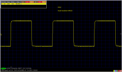
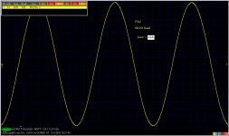
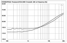
I have just measured a channel separation for PA4, which uses 2 separate power transformers and in fact there are 2 independent amplifiers in one box. It was difficult to get anything, but finally:
- one channel driven at 10W/6.8 ohm output power
- crosstalk to second channel is -128dB/3kHz, -123dB/5kHz, -117dB/10kHz. At low frequencies, crosstalk is below FFT bottom.
- one channel driven at 10W/6.8 ohm output power
- crosstalk to second channel is -128dB/3kHz, -123dB/5kHz, -117dB/10kHz. At low frequencies, crosstalk is below FFT bottom.
Oddly enough, I ran 8 units absolutely full bore plus for several years 6 nights a week, 6 hours per night. Never had one blow anything internal whatsoever. R14 opened on one unit, it was undersized for the dissipation. I do admit however, I threw out the cases and heatsinks that came with the kits, installed chimneys with 5 inch fans.Someone was talking about a SWTPC Tigersaurus recently: http://www.swtpc.com/mholley/RadioElectronics/Dec1973/RE_Dec_1973_pg44.jpg
Oddly enough I was looking in my junk...I mean supply boxes last week and found a Tigersaurus main PCB! If I remember correctly they would nuke an expensive set of outputs in a heartbeat, making the people I built them for very upset. Does anyone know if the rumor that one set Walt Jung's house on fire is true?
PMA...how did you layout the supply rails for the outputs, and how did you arrange the grounding star? I'm very interested in the input pair grounding scheme, both from the input and from the feedback.
jn
Congratulations PMA. I doubt that Carl and I could do better, or perhaps as well.
One of the compromises that I have had to make with Parasound is in layout.
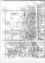
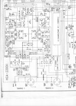
All of the JC series is personally done by my associate Carl Thompson, who also did the layouts of the Vendetta Research phono, Constellation phono, and even the CTC Blowtorch. (He is the T in CTC) He is an expert in layout and he also cares more about crosstalk than most designers. I have little control over the layouts of most of the Parasound products. They just get a 'simplified' schematic from me and everything else was generated in Taiwan, often by people I never was contacted by. It could be really frustrating at times. Here is the crosstalk of the HCA 3500. It is not perfect, but more typical of what I usually expect.
One of the compromises that I have had to make with Parasound is in layout.
All of the JC series is personally done by my associate Carl Thompson, who also did the layouts of the Vendetta Research phono, Constellation phono, and even the CTC Blowtorch. (He is the T in CTC) He is an expert in layout and he also cares more about crosstalk than most designers. I have little control over the layouts of most of the Parasound products. They just get a 'simplified' schematic from me and everything else was generated in Taiwan, often by people I never was contacted by. It could be really frustrating at times. Here is the crosstalk of the HCA 3500. It is not perfect, but more typical of what I usually expect.
Attachments
When they measure crosstalk, what do they use as a load? Resistive, inductive? Combo?Here is the crosstalk of the HCA 3500. It is not perfect, but more typical of what I usually expect.
jn
Congratulations PMA. I doubt that Carl and I could do better, or perhaps as well.
One of the compromises that I have had to make with Parasound is in layout.
I am sure you and Carl would make a similar result. There's a difference, A21 is a commercial design and you need to meet costs and expenditure demands. Mine was built in 3 + 1 pieces and there was no need to make it 'rational'. I admire value/cost ratio of both A21 and JC1.
Anyway, I am still interested in '2 transformers' discussion. With 1 common transformer, even if it had separate secondaries for L and R channel, I was never able to get the same channel separation as with 2 transformers (there must be a HF capacitive coupling in one transformer and probably LF voltage drop at low frequencies). I guess one transformer is for the lower cost reason?
Last edited:
- Status
- Not open for further replies.
- Home
- Member Areas
- The Lounge
- John Curl's Blowtorch preamplifier part II