Pretty much ignored is that some wire wound resistors can sing. If the coil isn't tight there can be movement and shifts in inductance and resistance. More worrisome in in loudspeakers is the much better known vibration induced noise in capacitors.
Can you actually generate enough voltage from vibration of a cap in a passive crossover to hear it in a speaker? Especially over the din causing the vibration?
Can you actually generate enough voltage from vibration of a cap in a passive crossover to hear it in a speaker? Especially over the din causing the vibration?
My loudspeakers put out a bit more than yours! It is not that they create voltage it is that they modulate value. The simple test is to apply a small current to a test capacitor inside the enclosure and look at the voltage. I did curves and will post if I find them.
Lynx EOL! The last Dale WW I got from Mouser were labelled Mills. If you really want tweaky try JN's noninductive assembly.
For those who didn't understand the singing, as the wire heats up it gets longer and breaks many bonds holding it in place. That often results in less cooling and hot spots. Hot spots increase THD.
For those who didn't understand the singing, as the wire heats up it gets longer and breaks many bonds holding it in place. That often results in less cooling and hot spots. Hot spots increase THD.
You can't do that to a capacitor and have it survive. Unless you're trying to form a lytic.The simple test is to apply a small current to a test capacitor inside the enclosure and look at the voltage. I did curves and will post if I find them.
Try that test again, but this time do it right

Seriously, you did mean voltage, no?
And within the enclosure is huge time varying fields, a consequence of spillage of field from the magnetic circuit. Haven't you ever stood an enclosure next to one of those old CRT style TV's? It's interesting to watch the impact the spilled field has on the tv picture when the speaker is playing loud.
You need to eliminate loop trapping at the capacitor itself.
Use coax to connect to the capacitor. At the capacitor, you need to run the coax core directly to the cap lead, and the shield return has to be connected to the opposite end of the cap by the use of a braid over the cap. This is of course, for axial capacitors.
This setup controls for external fields.
jn
JN,
Most of the current supplies normal folks have will not go above 25 volts open circuit! The magnetic field that distorts your CRT is pretty static.
As C dv/dt + V dc/dt = i at dc/dt =.01% 0f 10 uF at a scope input impedance of 10 Mohms, what voltage do you expect to see? And what magnetic induced voltage? (You can pick your own number for the flux induced into a scope probe attached to a capacitor stuck in the loudspeakers port.)
When I did the measurements my reference was a resistor.
JN,
Most of the current supplies normal folks have will not go above 25 volts open circuit!
So then, the voltage was 25 volts?
If you mean constant voltage, perhaps you should say constant voltage?
NO. As I said, the audio signal was causing CRT distortion. The dynamic effect was very clearly pronounced. All signals in the 36, 60, 120 hz areas caused significant beating of the picture, worst on the speaker side.The magnetic field that distorts your CRT is pretty static.
Your equationed statement has no meaning to me. Since you consistently speak of entities like -150 dB and such, and the experiment you now discuss has error sources orders of magnitude larger that that, I felt the experimental design needed discussion first.As C dv/dt + V dc/dt = i at dc/dt =.01% 0f 10 uF at a scope input impedance of 10 Mohms, what voltage do you expect to see?
And what magnetic induced voltage? (You can pick your own number for the flux induced into a scope probe attached to a capacitor stuck in the loudspeakers port.)
First, I'd baseline the experiment. Use a solid piece of wire in lieu of the capacitor to determine the flux trapped induced voltage. I do not recall you baselining an experiment before, although I still remind you..
And, the "magnetic induced voltage" was actually the acceleration voltage necessary to bend a 10 KeV electron from it's intended path into the shadow mask holes of the next color over. Say, roughly 1mm side movement out of 500 mm acceleration at 10kV. 1/500 of 10kV is 20 volts (assuming sin(x) for small x of course.) 2 to 5 volts is probably sufficient to provide a just noticeable effect without significant color change, diversion into the mask between pixels.
Meaning what? You tried to baseline using a resistor? What value, what current? And how did you get around the extreme low pass filter created by the resistor with a power supply voltage source connected?When I did the measurements my reference was a resistor.
There are too many confounders in your setup, rending the results extremely questionable.
jn
Last edited:
A voltage source will have a low output impedance, that is why a voltage limited current source is better.
Not worth the argument Demian is capable of reaching his own conclusions.
You've made a claim that the value of a capacitor is modulated by the spl within a cabinet.
You base that claim on a test which has confounders so significant that without proper controls, the claim must be simply discounted.
I have proposed a test design which removes them. You ignore that advice.
jn
You base that claim on a test which has confounders so significant that without proper controls, the claim must be simply discounted.
jn
I've seen this several times in print, a capacitor suspended on long leads over a driver running high SPL. I never tried the spark test, it does nicely separate the electrical from acoustic stimulus and the peak SPL is pretty high. In fact the results can be unambiguous with time windowing, I think I'll put it on the to do list.
Last edited:
I never tried the spark test,
What is the spark test?
Is it a capacitor // to an air gap fed with a high voltage up to the gap’s breakdown voltage (test the cap during the discharge)?
George
What is the spark test?
Is it a capacitor // to an air gap fed with a high voltage up to the gap’s breakdown voltage (test the cap during the discharge)?
George
Exactly, the method is to build up a charge on a low inductance capacitor and to dump it all at once into a spark gap. The trick is how to trigger the gap. The easy method is with a small flash transformer spark to one of the electrodes. Very 1930's.
The EMI travels faster than the shock wave so you might be able to tell them apart.
JN, I am surprised you were unaware of vibration issues in film capacitors. I thought it would be obvious as the yield strength of aluminum and most dielectric plastics is pretty apparent.
SY probably knows the yield strength for all the common ones by memory. The foil is going to be work tempered and George will have that.
Thank you Ed!Exactly, the method is to build up a charge on a low inductance capacitor and to dump it all at once into a spark gap.
The trick is how to trigger the gap
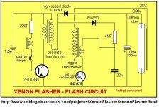
Here you are and it does a repetitive trigering.
Two capacitors for you for this ambitious testing (plus a resistor and why not a transistor too).
Shielding from the transformer fields will be required.
Xenon Flasher
I never tried the spark test, it does nicely separate the electrical from acoustic stimulus
The EMI travels faster than the shock wave so you might be able to tell them apart.
I don’t know what testing equipment you have in mind but I find it difficult to think of it as an easy task.
There is more than one mechanism that can generate a shock wave in each layer.
Once generated in different depths, in different layers, shock waves have to travel a short distance into the multiplayer- multimaterial construction (add the complexity of the interlayer reflections).
You are planing to detect the pressure pulse on the cap surface, no?
A dozen beers donation placed on the table as a success stimulus

George
Attachments
Last edited:

"This project generates 350V DC and stores the voltage in a large electrolytic. This voltage will not kill you, but will deliver a nasty SHOCK! For this reason, the project has a great benefit. It will teach you to work very carefully on equipment with high voltages and if you do get a shock, you will appreciate electricity EVEN MORE!"
By George you've got it. At 30 cm you have almost a millisecond difference between EMI and pressure wave.
In Latin it is improper to end a sentence with a preposition. For some arcane reason this rule carried over to English. So when someone corrects you for ending a sentence with a preposition such as "with" just add at the end mother F'r. (Old bad joke )
Brad that circuit shown is much better then the Popular Electronics version that used a direct AC line powered voltage doubler to the power supply capacitor. The circuit shown requires a transformer that would be difficult to get until you realize the complete circuit is available in any disposable camera. (If you can still find one.)
- Status
- Not open for further replies.
- Home
- Member Areas
- The Lounge
- John Curl's Blowtorch preamplifier part II