Demian one of my AX articles that is still on their site is a 60 Hz LC power resonator. The circulating currents are quite high. One of the easiest peak voltage improvements. Made a noticeable and measurable improvement.
Link or copy?
What kind of parts did you use? I can see the currents getting enormous. Would be fun with a super conducting coil. . .
Steve Smith's patent points out that a rectified supply doesn't get its power at the fundamental, something that makes all this stuff more complex and interesting.
Of course the analogue version of the digital waveform won't be a 'perfect' square wave, there will a 'rounding' of the corners in some sense. Precisely how that rounding will manifest is then dependent on a whole lot of implementation variables.
QUOTE]
What? what, what are you trying to say Frank. There is no version of a digital waveform, a digital waveform as you call it consists of numerous harmonics, look up knee frequency and read some of Howard Johnson and Eric Bogatin's stuff, learn from the real Digital signal guru's instead of sprouting audiophile weirdness.
Rounding of the square wave is more desirable than ringing.
Except this is audiophile wierdness ala Wadia. Interpolating PMA's data with a smoothly rounded square wave is mathmatically wrong and will generate unwanted image tones.
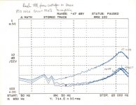
So the cursor at 714.5nV is referred to the input, divided by the gain of times 40, as about 18nV/sq rt Hz? Or, wait, I see that the BW is 50Hz, so I guess we account for 7.07 sq rt Hz?More office cleaning, here is a noise plot I did years ago using a Shure style MM cart with the stylus removed as a source impedance.
This in any case certainly underscores the importance of low parallel noise, as the LT part does rather badly at high frequencies. Do you recall what the actual cartridge model was?
Last edited:
So the cursor at 714.5nV is referred to the input, divided by the gain of times 40, as about 18nV/sq rt Hz? Or, wait, I see that the BW is 50Hz, so I guess we account for 7.07 sq rt Hz?
This in any case certainly underscores the importance of low parallel noise, as the LT part does rather badly at high frequencies. Do you recall what the actual cartridge model was?
I think I still have it in a junk bin at home, IIRC it was not a Shure but was very close to a V15 in inductance and recommended cap load. Thes e were just for a relative comparison, I guess there is enough info to get the actual numbers. Good old HP pen plotter, the only output device available.
Scott,
In looking back on this thread there was an issue that we didn't quite settle on.
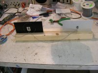
Attached is the picture of the setup. A current source of 1 amp was used and the voltage across the resistors was 7.32 and 7.31 volts. Both pieces are .125" 5052 aluminum 3' x 6" with the hole .125" centered. The finish was mill finish cleaned with a lye bath. Paint is Rustoleum Flat Black spray paint both sides. Temperatures measured using a bead thermistor in direct contact at the heatsink back just under the mounting bolt were 39 & 42 C.
In looking back on this thread there was an issue that we didn't quite settle on.
Attached is the picture of the setup. A current source of 1 amp was used and the voltage across the resistors was 7.32 and 7.31 volts. Both pieces are .125" 5052 aluminum 3' x 6" with the hole .125" centered. The finish was mill finish cleaned with a lye bath. Paint is Rustoleum Flat Black spray paint both sides. Temperatures measured using a bead thermistor in direct contact at the heatsink back just under the mounting bolt were 39 & 42 C.
Attachments
Last edited:
E Simon,Very funny.
Some people actually take all this seriously. What a waste. Just put on the music and relax.
(I was looking at the current heat on the new Bybee thread.)
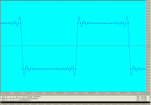
Yes, that's fine. In the digital world everything behaves as it's meant to, providing no-one has made a really silly mistake - or is attempting to do strange filtering, to pre-process the waveform before it hits the DAC, in order to compensate for the latter's 'inadequacies'.For Frank, 1 kHz square with 44.1kHz sampling. Only 2 "digital values" are present. Not sure it these explanations would make any sense in this particular case.
I've gone through the exercise of creating a perfect digital square wave, just 2 values as you say, and then passing that through digital equalisation, with as close to perfect pass band as can be specified. And, out pops a digital waveform that looks exactly as you have shown - the application of the filter has demonstrated the ringing, or "rounding of the corners" necessary so that frequencies beyond the Nyquist limit don't intrude. All in the digital domain ...
However, this only tells us what then theoretically happens in the analogue reconstruction arena, - what does happen, especially with "from hell" waveforms, is a function of the designer's mindset, and the competence of the implementation ...
Anyway, this is all by the way stuff, something mentioned in relation to how real systems behave, or should behave, in the real world when audio signals coming through hit the bump stops ...
Just picking up on the word 'relax' - the last thing I want from listening to music is to relax ... normally,Some people actually take all this seriously. What a waste. Just put on the music and relax.
(I was looking at the current heat on the new Bybee thread.)
. Music should grab me, be an intense, powerful, involving experience. If I'm sitting next to a live jazz trio, even if they're playing layback material, the last thing on my mind is feeling like having a bit of a snooze ...There is no such thing, there are no drivers out there that can switch from zero to supply in zero time, the wave always has a slope (true square waves only contain odd harmonics). The steeper the slope the more problems you have, as it is the slope that determines a signals speed and harmonic content. So you have NEVER created the perfect square wave, it is a physical impossibility.I've gone through the exercise of creating a perfect digital square wave
Have a look at some DDR MEMORY(1,2 or 3) waveforms.
Digital filtering? generally you add some form of termination, series, parallel thevorin or a mixture of termination, its matching the drivers output to the receivers sink (or source capabilities) and allowing for the effects of the transmission line (the wires and cable carrying the signal). For critical stuff you shove it on an inner layer surrounded by return paths (gnd planes) so you get quasi TEM wave propagation (stripline) though the wave moves marginally slower on inner layers of a PCB, than it does on the outer two layers, again a factor you have to think about when matching signal electrical lengths.
Last edited:
marce, there are pieces of software out there that can do this, trivially easily - called digital editors. I can make a digital waveform do whatever I want to, if so inclined - 'manufacture' a valid sound track at sample rates above 1Mhz, say, with 'pure' square waves encoded on that! Pity the poor DAC that may have to make sense of that, but as a technical exercise it's a no-brainer.There is no such thing, there are no drivers out there that can switch from zero to supply in zero time, the wave always has a slope (true square waves only contain odd harmonics). The steeper the slope the more problems you have, as it is the slope that determines a signals speed and harmonic content. So you have NEVER created the perfect square wave, it is a physical impossibility.
If one can create a digital waveform, by whatever means, that is precisely what you want it to be, then it becomes worthwhile considering what the impact of that will be on circuitry that it may interact with ...
Edit: BTW, I never said a perfect square wave, I said a perfect digital square wave
Last edited:
- Status
- Not open for further replies.
- Home
- Member Areas
- The Lounge
- John Curl's Blowtorch preamplifier part II