Bcarso, while high Gm is not a bad thing, it also tends toward low Vp and this is not so good. That is why, we tend to use very high Idss-medium Gm devices in order to get a greater Vp so that the input device operates more like a real jfet.
So many words for Gm = 2*Idss/Vp
Making sense now?
")
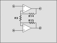
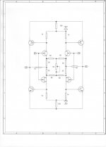
Godfrey, I appreciate your efforts. What you have shown are basically two independent amplifiers side by side. Op-amp analogy of it would look like the one in the picture on the left.
What I was referring is the topology in the picture on the right. (I've split the feedback resistor in two for the sake of symmetry).
Attachments
The more I think about it, the more confused I get ...
John, your 4Q topology, what is it? Is it two complementary differential amplifiers on top of each other or is it two amplifiers of the topology on the right, cross-coupled? Or is it something inbetween?
John, your 4Q topology, what is it? Is it two complementary differential amplifiers on top of each other or is it two amplifiers of the topology on the right, cross-coupled? Or is it something inbetween?
Attachments
So many words for Gm = 2*Idss/Vp
And yet . . . so few symbols for something so eloquently uttered
Yet, the equation does not tell you specifically what you are looking for, which is a HIGH Vp. A HIGH Vp gives the input fet some voltage to lower its intrinsic input capacitance, as well as to actually get into the 'pentode' region rather than the 'triode' region. I cannot say that this is super important, but lower intrinsic capacitance is a good thing.
Think of your equation as:
Vp= 2*Idss/Gm Then the only way to get high Vp and high Gm is with VERY HIGH Idss. So called analog switch based devices do this pretty well.
Think of your equation as:
Vp= 2*Idss/Gm Then the only way to get high Vp and high Gm is with VERY HIGH Idss. So called analog switch based devices do this pretty well.
Transconductance of 325mS at 120mA, but far less pretty under 10mA drain current.
Two K170GR in parallel would have an impedance under 25R, with J74 available.
(a relic like me still has a bundle of Grey J72/K147, and diy folks can still opt to locate NOS complementary parts with high gm numbers, as e.g. J104/K364)
I'm not all that high on the depletion mode DMOS either. They can be nice for current limiter duty as hollow-state anode loads, especially cascoded themselves, with minimal parts and reasonable (albeit not guaranteed) noise. But in the example part, if the transconductance goes as the square root of drain current the 10mA ought to still be a healthy ~94mS or so. Compare this to a 4391 or other selection from what National used to designate as Process 51.
At least the voltage withstand for the DMOS part is large. Of course there are no P parts. There are lots of enhancement mode P parts thanks to the Benjamin Franklin direction of current flow (pardon that somewhat cryptic remark) but they suffer from low carrier mobility like everybody else.
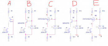
What looked fairly promising were some fairly old but still available Zetex enhancement-mode medium-voltage medium-geometry parts with floating ~7V bias. There are P versions not too bad as well. I even bought some. I think it may be time for some schematics and sim results, even maybe (gasp!) some measurements. You are warned that my sim does not handle the transition from triode region to pentode very accurately, so YMMV as well as my own.
These might make it easier to explain why one would entertain the driven-cascode approach, and why bipolars are somewhat cumbersome for biasing. They are otherwise good for high gm at moderate currents.
The opamp portrayal is fine. If you drive one input and tie the other to common you reproduce the behavior of the discrete circuit, including the unequal-magnitude outputs relative to common.Godfrey, I appreciate your efforts. What you have shown are basically two independent amplifiers side by side. Op-amp analogy of it would look like the one in the picture on the left.
What I was referring is the topology in the picture on the right. (I've split the feedback resistor in two for the sake of symmetry).
If you consider the opamps as current feedback amps the comparison is even closer. As I remarked earlier the bipolar emitter connections are not crucial to circuit operation, but the arrangement is felicitous for allowing the JFET loads to be larger without the need for a bias voltage; it is also fairly low parts count. This allows the open loop gain at the bipolar bases to be larger than if we simply had a resistor from base to emitter as the JFET drain loads, which would make each quadrant essentially a complementary feedback pair, with a JFET and a bipolar instead of the typical two-bipolar topology. But in the CFP case, the 10mA or so of the JFET quiescent current must produce about a 0.7V drop, which is a rather small base-emitter resistor (~70 ohms). This entails a low open-loop voltage gain for such a CFP at that point (40mS * 70 ohms is only 2.8).
With 1k loads, absent the loading by the mosty-undegenerated bipolars, the corresponding open-loop gain is a healthier (-) 40. With some R in the sources this goes down a little.
The opamp portrayal is fine. If you drive one input and tie the other to common you reproduce the behavior of the discrete circuit, including the unequal-magnitude outputs relative to common.
Jeez, bcarso, I've known this for something like 30 years or so ..
What I wanted to see was, quoting from my OP:
formula using exact values from the John's schematic how to calculate gain for both sides
which nobody have produced so far.
Schematic in question is this one.
Attachments
Last edited:
which nobody have produced so far.
You've been given all the info you need plus some pretty good hints- John has given the recommended gms as well. Why don't you derive it?
Amen.You've been given all the info you need plus some pretty good hints- John has given the recommended gms as well. Why don't you derive it?
Suffice it to say however that there is enough open loop gain, absent a lot of output loading, to treat the thing as if it were nearly ideal. The ramifications of the network in the center are fairly trivial, but to produce an expression with each and every resistor accounted for will be fairly hairy-looking. The approximation of all four JFET sources directly pairwise-commoned will not be that bad, although real-world matching would be unlikely.
And don't worry about the bipolars' shared emitter loads. It makes the circuit look more interesting though. The effect is to cut the transconductance of each part about in half, as each sees the other's r sub e, and since they run at high-enough emitter currents the loss due to the 100 ohm resistors is small. The diminution of open loop gain of a given half will I think be compensated by the cross-coupling.
Buzzforb, asked a relevant question earlier, as to WHY we did not just use bipolar transistors, instead of jfets?
Well, we DID! For the first 5 years, (1968-1973) I only had complementary matched bipolar transistors to work with, and we developed similar circuits with bipolar transistors. In the same time period, several other designers started to make complementary differential input stage circuits for both preamps and power amps.
When jfets became available, they had several advantages:
1. They were easier (in principle) to bias.
2. They had virtually no input current, so higher input resistors would be practical.
3. The transfer function of a fet diff pair generates less higher order odd harmonics.
4. jfets are relatively RFI insensitive.
Once complementary jfets became available, about 40 years ago, I jumped on them and with them, created my most successful circuits.
It is a shame that great jfets are harder to find, and have gone up in cost, but that is not a problem that I can fix. Actually, most really good bipolars are hard to get, too. It would appear that the most popular bipolars, today, are devices that I used more than 40 years ago. This is progress?
I'm not all that high on the depletion mode DMOS either. They can be nice for current limiter duty as hollow-state anode loads, especially cascoded themselves, with minimal parts and reasonable (albeit not guaranteed) noise. But in the example part, if the transconductance goes as the square root of drain current the 10mA ought to still be a healthy ~94mS or so. Compare this to a 4391 or other selection from what National used to designate as Process 51.
What would indicate less than ideal performance from the depletion mode devices? I have had no negative experiences with them as cascodes on some products in production for a while. What have I missed?
Moving on: (if possible) Let me show what we USUALLY use for the 4Q input stage to cascode it. There are a number of advantages, including more real voltage across the input part to lower and linearize its inherent input capacitance.
Easier part selection, only 3 extra resistors (minimum) added, better high voltage standoff.
Easier part selection, only 3 extra resistors (minimum) added, better high voltage standoff.
Attachments
...or 5 in this case, with the second stage cascoded as well. How come values aren't shown for those resistors? Most of the others have values assigned.only 3 extra resistors (minimum) added
Also, as an aside, the gain seems rather high for a modern line stage - about *22 if I got the sums right. I noticed similarly high gains in the other circuits you posted too. Is this to cater for old tuners and whatnot that may only have an output of 250mV or so?
Seriously? I remember >30 years ago integrated amps tended to have an input sensitivity of around 250mV for full output. Then CD came along with the 2V max output standard. I would have thought everything else would have moved in the same direction in the interests of compatibility, maybe taking 700mV or so average output as a target for analogue sources.but 150 to 250mV is the norm now for non digital stuff.
(not that I've been paying attention the last couple of decades - I quit buying hifi magazines around the time I started buying baby food, not coincidentally)
It poses the question of what next. As you say, the jfet possibilities are quickly drying up, if youdont have large personal stash. Do you have any current product that you are ppersonally excited about that uses other products than the typical low noise jfets.Buzzforb, asked a relevant question earlier, as to WHY we did not just use bipolar transistors, instead of jfets?
Well, we DID! For the first 5 years, (1968-1973) I only had complementary matched bipolar transistors to work with, and we developed similar circuits with bipolar transistors. In the same time period, several other designers started to make complementary differential input stage circuits for both preamps and power amps.
When jfets became available, they had several advantages:
1. They were easier (in principle) to bias.
2. They had virtually no input current, so higher input resistors would be practical.
3. The transfer function of a fet diff pair generates less higher order odd harmonics.
4. jfets are relatively RFI insensitive.
Once complementary jfets became available, about 40 years ago, I jumped on them and with them, created my most successful circuits.
It is a shame that great jfets are harder to find, and have gone up in cost, but that is not a problem that I can fix. Actually, most really good bipolars are hard to get, too. It would appear that the most popular bipolars, today, are devices that I used more than 40 years ago. This is progress?
- Status
- Not open for further replies.
- Home
- Member Areas
- The Lounge
- John Curl's Blowtorch preamplifier part II