Almost everything is easy, once you come to understand it, or even think it possible.
33 years ago, I had to show Dr. R.G. Meyer a simplified version of this ckt, in order for him make a better low noise balanced input preamplifier. He, too, was caught up in the 'limitations' of the OP AMP possibilities at the time. It was used in a cryo experiment at LBL.
33 years ago, I had to show Dr. R.G. Meyer a simplified version of this ckt, in order for him make a better low noise balanced input preamplifier. He, too, was caught up in the 'limitations' of the OP AMP possibilities at the time. It was used in a cryo experiment at LBL.
@ elektroj
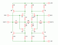
Here's a "bare bones" version of the circuit. The closed loop gain is set by R3, R14 and R15.
Vout1 = Vin1*(r14+R3)/R3 - Vin2*R14/R3
Vout2 = Vin2*(r15+R3)/R3 - Vin1*R15/R3
So with the values given:
Vout1 = 11*Vin1 - 10*Vin2
Vout2 = 11*Vin2 - 10*Vin1
Making sense now?
")
Here's a "bare bones" version of the circuit. The closed loop gain is set by R3, R14 and R15.
Vout1 = Vin1*(r14+R3)/R3 - Vin2*R14/R3
Vout2 = Vin2*(r15+R3)/R3 - Vin1*R15/R3
So with the values given:
Vout1 = 11*Vin1 - 10*Vin2
Vout2 = 11*Vin2 - 10*Vin1
Making sense now?
Attachments
Last edited:
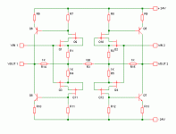
You mean on the input JFETs, something like this?local cascodes
I'd expect lower input capacitance, but possible stability problems. Haven't a clue about the effects on open loop gain and linearity.
Anybody else can shed some light?Attachments
Wonderful, Godfrey! By the way, what schematic drawing program are you using? I like it, as mine is too complex.
You have SHOWN why there is a difference in the two outputs, WHEN only a single ended drive is used.
Someday, I hope to show how the late Jim B. 'solved' this problem, one that I could only correct with relays.
You have SHOWN why there is a difference in the two outputs, WHEN only a single ended drive is used.
Someday, I hope to show how the late Jim B. 'solved' this problem, one that I could only correct with relays.
You mean on the input JFETs, something like this?
I'd expect lower input capacitance, but possible stability problems. Haven't a clue about the effects on open loop gain and linearity.
The Csanky bootstrapped cascodes in a circuit do have a negative input impedance at high frequencies, but I've found this to be usually easy to compensate with some lumped C at the gate to common. However the reduction in input capacitance modulation with voltage swing is very advantageous for distortion reduction at high frequencies.
Sorry to be slow in responding on the formulae, and thanks to all for the work while I was sleeping
I have done some simulations with the upper half circuit which may be worth "publishing", but I think the gist of circuit operation is emerging. Remember that this is a relatively high feedback design, despite some of the inputs being low impedance open-loop. However it is fast enough that distortion is not much changed at 10kHz compared to 1kHz, and this is without cascoding. More at 11.
Hi John.By the way, what schematic drawing program are you using?
It's the free version of SIMetrix SIMPLIS. I find it a lot easier to use than LTSpice. I'm not sure if there's a MAC version though.
Looking forward to that!Someday, I hope to show how the late Jim B. 'solved' this problem, one that I could only correct with relays.
Thanks. I suspected something like that, but hadn't thought it all the way through.The Csanky bootstrapped cascodes in a circuit do have a negative input impedance at high frequencies, but I've found this to be usually easy to compensate with some lumped C at the gate to common.
Last edited:
Walt Jung did the historical research about Csanky and corresponded with him. A lot of material was uncovered after I discovered that the base current recovery topology most still attribute to Baxandall and Shallow was in fact invented by Frank Boxall, who passed away recently.Thanks. I suspected something like that, but hadn't thought it all the way through.
All of these circuits with such techniques are susceptible to the mechanism to some extent. In this case it is modified by the closed loop configuration a good deal. Remember of course (as I'm sure you know, but mentioning this for other readers who may not) that the added FET needs a higher pinchoff voltage than the input device to work well.
The added advantage of the Csanky circuit is to much reduce the signal-induced self heating of the input devices with voltage swing. When the overall circuit is driven single ended there is no longer means of inducing tracking dissipation shifts with signal.
Demian I think remarked, a while back in here, that the devil is in the details of getting this topology and related ones to do multiple duties: all combinations of single-ended/balanced inputs/outputs. And in particular the availability of a polarity reversal for those who hear the Wood Effect (no relation btw) requires that the gains be made the same. The higher the closed-loop gains are, the smaller the relative disparity between output magnitudes, but it would still be appreciable for the values shown.
OK, I'm feeling ignoranter and ignoranter by the moment now.
I'd never heard of Csanky before, but a quick search turned up some of Walt's posts. Likewise, I had no idea the "Baxandall super-pair" was actually invented by Frank Boxall.
BTW, what's the Wood Effect? (sometimes Google don't help)
I'd never heard of Csanky before, but a quick search turned up some of Walt's posts. Likewise, I had no idea the "Baxandall super-pair" was actually invented by Frank Boxall.
BTW, what's the Wood Effect? (sometimes Google don't help)
A real concern is the Gm of the respective devices in the self cascode. I tend to prefer to use normal cascodes or folded cascodes rather than the self-cascode. I think it is best to use a LOW Gm cascode part and a HIGH Gm part for the input part. This is subtle territory however, and I have not made extensive measurements of the difference.
The advantage of the 'normal' cascode is that you can increase the voltage across the input device, thereby lowering and linearizing the feedback capacitance across the input fet.
From my understanding, this 'self cascode' or as you call the Csanky cascode was first used as the FETRON, tube replacement jfet cascode (a very high voltage jfet was used as the cascode) fore replacement of the input tube for VTVM's back in the late 60's. I once made the same basic design for the GD back in 1973, to experiment with open loop subjective performance. They still preferred tubes, however. '-)
Last edited:
BTW, what's the Wood Effect? (sometimes Google don't help)
That's the hyper-important "absolute polarity" without which your hifi sounds like doo-doo. There's a loony guy in Boston (I think) who's been riding that hobby horse for years.
I once made the same basic design for the GD back in 1963...
Are you sure about that date?
BTW, what's the Wood Effect? (sometimes Google don't help)
See Clark Johnsen's book: "Wood Effect: Unaccounted Contributor to Error Confusion in Acoustics and Audio" ISBN 0929383001
I see a few copies for sale online. One seller is generously offering to part with one for over 3k US. I suspect that will be on the shelf for some time to come.
I think there is also an AES preprint by Johnsen out there.
In short, the effect is detecting absolute polarity via a subtle perceptual difference. Some people are allegedly more sensitive to it than others. Of course the recording process has to preserve it throughout, so having a net noninverting reproduction system is no guarantee of getting a blow instead of a suck. So some preamps provide the function of polarity inversion so the listener can determine which sounds best for a given playback of something.
cjwoodeffect
(for photographers, there's also the wood effect for infrared images, Robert, not Charles)
(for photographers, there's also the wood effect for infrared images, Robert, not Charles)
Last edited:
Actually Rich May pointed out to me years ago that he felt a lot of the supposed effect could be associated with transducers with significant second harmonic distortion. Jim Boyk takes it seriously and mentions on his LP covers that one might try reversing both pairs of speaker leads for better results.
At one point I was considering a "high-end" product that would consist of mercury displacement relays to accomplish the speaker lead reversal. I still have some of those big clunky mothers, some things requiring very careful disposal indeed. And there are some new relays that probably obviate the need for the Hg ones anyway.
At one point I was considering a "high-end" product that would consist of mercury displacement relays to accomplish the speaker lead reversal. I still have some of those big clunky mothers, some things requiring very careful disposal indeed. And there are some new relays that probably obviate the need for the Hg ones anyway.
Actually Rich May pointed out to me years ago that he felt a lot of the supposed effect could be associated with transducers with significant second harmonic distortion.
Exactly right. That's where I've been able to hear it, anyway.
Ta. I'll believe that can be audible, although I've seen some absolute rubbish written about it."absolute polarity"
I remember one particular website on the subject that just screamed "quack-site" - a single web page about 2000 lines long with the same stuff repeated over and over in every imaginable font size and color. Not a good way to get yourself taken seriously, IMO.
IIRC there was a thread about it here a couple of years ago, started by the same guy.
- Status
- Not open for further replies.
- Home
- Member Areas
- The Lounge
- John Curl's Blowtorch preamplifier part II