No silly, it was Al Dentay. or....Harry Viderchay. Bang/zoom.
That beats Jack Mehoff hands down.
se
What jargon?
 I read through the whole thing, that was plain and simple english.
Now ya know why they shim MRI's to 1 part in 10-7 accuracies..and why they use persistent switches to maintain current.
jn
Agreed, what jargon? It was simple enough for me to understand it all.
To begin with NMR is jargon. Just because you know and can read the big words without sub-vocalization does not free them from being jargon.
Now how do I get a 2 Tesla magnet to lubricate the proton bonds in the acoustic environment?
The second point is that real science based explanations build on what you already know and make sense!
Now when someone spams stuff using a different name and the mud starts slinging, is it a wonder the useful folks leave?
So back to the finesse of an old obsolete circuit that for some strange reason is still being used.
ES
(maybe one of these days, SY can give a lecture on NMR/MRI imaging)
Yes certainly, I will post some MRI pictures for diagnosis if needed. ;-)
To begin with NMR is jargon....
No, definitely not.
circuit analysis
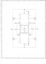
So getting back to the schematic from post 38464: if you just consider an upper or lower half, and suppose for the moment that the active devices are voltage-controlled current sources, the topology is essentially complementary feedback pairs as current feedback amplifiers, connected "back-to-back". The difference in output magnitudes when only one side is driven is easy to see based on the input section side having the traditional resistor ratio + 1 gain, and the other managing just the resistor ratio. If you sense the differential voltage at the outputs you get the same magnitude as when you look at the output of a single side with half of the cross-coupling feedback divider resistance tied to common.
One unusual thing is the treatment of the bipolars (in this embodiment), which have their emitters tied together and the total emitter current supplied by the 100 ohm resistor to a given rail. It's tempting to suppose that the cross-coupling in this fashion is in some way key to the circuit operation, but I think not: it doesn't hurt, but the main advantage is the setting of stable bipolar quiescent currents, compared to the less-certain simple pairing of CFPs. And it allows the input devices to develop a substantial open-loop voltage gain at the bipolar bases, without requiring some constant-voltage device in each emitter. With the arrangement shown each bipolar sees the emitter impedance of the other, which at healthy currents is low. Hence locally the gm of the bipolar is halved, but still plenty high for what the likely currents are.
When we add the complementary half to the other we also take care of supplying current to the JFETs as well as getting the effect of paralleling for lower noise, without requiring additional resistors or current generators.
Attachments
spooked
In the early '80s, I had lectures on NMR, visited Philips medical systems to see the first prototypes.
(even recall the status fight club between the regional hospital participants, about who was to be granted permission to get one, as it cost twice the amount of a CT scanner)
Back then it was called NMR imaging, and the first operational ones were named NMR scanners.
Fortunately, they only carried numbers and the brand name, so there was no need to remove a sticker a couple of years later.

So getting back to the schematic from post 38464: ..........The difference in output magnitudes when only one side is driven is easy to see based on the input section side having the traditional resistor ratio + 1 gain, and the other managing just the resistor ratio. If you sense the differential voltage at the outputs you get the same magnitude as when you look at the output of a single side with half of the cross-coupling feedback divider resistance tied to common.
this is exactly what I said, but you explained it a bit differently and perhaps more clearly. I was told my explanation was too general and my example using opamps was irrelevant...due to..using evil opamps I guess and my simplified example taken too literally.
Some were unable to recognize it was deliberately simplified and that my resistors R1 and R2 didnt relate directly to part assignments in the schematic. also because I stated that I hadnt yet studied the schematic, rather just stating a more general situation that occurs, this somehow made the supposition irrelevant...
I think several understood you and didn't comment. I just returned to looking at it, almost for recreation, after thinking about it for a while, and did so without documenting prior art as it werethis is exactly what I said, but you explained it a bit differently and perhaps more clearly. I was told my explanation was too general and my example using opamps was irrelevant...due to..using evil opamps I guess and my simplified example taken too literally.
Some were unable to recognize it was deliberately simplified and that my resistors R1 and R2 didnt relate directly to part assignments in the schematic. also because I stated that I hadnt yet studied the schematic, rather just stating a more general situation that occurs, this somehow made the supposition irrelevant...
oh I wasnt claiming 'prior art', more affirmation, my apologies if it seemed that way. you did explain it more clearly and in more correct language and I appreciate that
I was confused/frustrated at the lack of (public ) understanding despite re-framing it several times. I even provided pictures 
I was confused/frustrated at the lack of (public
) understanding despite re-framing it several times. I even provided pictures
Last edited:
oh I wasnt claiming 'prior art', more affirmation, my apologies if it seemed that way. you did explain it more clearly and in more correct language and I appreciate that
I was confused/frustrated at the lack of (public
Sometimes we just don't get any respect at all
indeed, but then some may say the same of myself sometimes when i'm in blunt-mode. it made me second guess myself over something that I thought was pretty elementary.
offtopic: can anyone suggest a nice composite jfet or bipolar + opamp circuit for an ADC input stage (balanced) and microphone preamp for measurement purposes? I intend to put something together with PCM4222 and wondered if I could trick up the lme49724 with a few discretes. also have some LMP8350 that may be enlisted. measurements for digital crossover setup, as well as perhaps basic line level characterization
offtopic: can anyone suggest a nice composite jfet or bipolar + opamp circuit for an ADC input stage (balanced) and microphone preamp for measurement purposes? I intend to put something together with PCM4222 and wondered if I could trick up the lme49724 with a few discretes. also have some LMP8350 that may be enlisted. measurements for digital crossover setup, as well as perhaps basic line level characterization
Last edited:
I get them from Acoustic Dimension over in the Netherlands.
Acoustic-Dimension, high-end audio and components for tube audio
se
Thanks Steve
can't find them on the website, seems they don't sell them anymore. Any part number that I can ask Peter about?
Edited:
Thanks SE, you already answered on Post #38522
Last edited:
The difference in output magnitudes when only one side is driven is easy to see based on the input section side having the traditional resistor ratio + 1 gain, and the other managing just the resistor ratio.
bcarso,
I am dumb. Would you, please, educate me and show me the formula using exact values from the John's schematic how to calculate gain for both sides?
Don't just say it's traditional, easy, this side, that side, other side etc. Show it.
Thank you!
Last edited:
Not so easy, is it?
Not like simple op amp examples. Yet it offers certain advantages such as balanced and unbalanced inputs and outputs, a sort of symmetrical elegance, and pretty low distortion and noise, without too much negative feedback being necessary.
I have been looking for clear images of certain spec sheets to show how jfet biasing in this circuit is done properly. Still can't find any.
Not so easy, is it?
Actually it is, if electoj follows my hint. Symmetry simplifies many problems in physics and electronics.
- Status
- Not open for further replies.
- Home
- Member Areas
- The Lounge
- John Curl's Blowtorch preamplifier part II