Tubes are better.
Probably not for MC input. Other than that, this is what my ears tells me (and the data sheets) …
")
Don't build BLOWTORCHES. I have said this, over and over.
Trust me, we don't ! Why should we?
Counting out that piece of info, why the sudden urge to give us that piece of advice?
Magura
Tubes are better.
Counting out that piece of info, why the sudden urge to give us that piece of advice?
And THIS is good advice.
How much Scott? Is it in the spec sheets? Is it better to current CLIP? Please maintain a sense of proportion, and save everyone a lot of grief. It is Erno Borbely who runs at Idss and above on a regular basis, not me.
However, thanks for the input. It might keep me out of trouble in future.
However, thanks for the input. It might keep me out of trouble in future.
How much Scott? Is it in the spec sheets? Is it better to current CLIP? Please maintain a sense of proportion, and save everyone a lot of grief. It is Erno Borbely who runs at Idss and above on a regular basis, not me.
However, thanks for the input. It might keep me out of trouble in future.
SPICE gives more or less the right answer, but there are more than one way to skin the line stage cat. I still don't think all the subtle issues of the common-mode vs differential offset have been brought out.
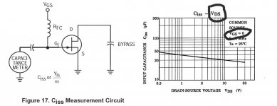
Why don't you give us the answer, Scott. The data sheet shows me 30pf at 10V Vds. What do you know that the data sheet doesn't tell us? Look, I'm getting tired of asking questions. Give the answers or let it go.
John, you are having a bad day, Ciss has little to do with Vds. OK for the benefit of everyone I will post directions for getting Cgd and Cgs from Ciss and Crss using the datasheet graphs.
Unfortunately some of these might be equally obsolete, I was thinking of things like the old E410 series from Siliconix which might be available from Linear Systems. The noise gets down to 3nV or so and the C's are only 1-3pF. By linearity I mean gos. The input Vgs-Id transfer function is the same square law for all FET's.
EDIT- Hand matched 2SK222's would give you a good go too. 10mS at 1mA and only 8-10pF.
The first rule of marketing is to be TOTALLY aware of the competition!
Well, back to work. I hope that everyone has read their Toshiba Audio jfet spec. sheets. It implies that at Idss for almost any part in the series, the input capacitance is essentially the same and varies with Vds, in a serious way. However, for the most part, Vds is high enough that the Cin and the change in Cn with input voltage is minimized. That is, at least where the Blowtorch circuits are operated.
For the BLOWTORCH, which is the title of this thread, and similar circuits, Idss is important, and high Idss is much better than lower Idss for THIS application. Other designs, like the JC-2, either the Levinson or Parasound, or the JC-80, Idss can be lower on the input stage without much loss. Generally, for commercially made products that are manufactured offshore, we operate around 2-4ma, rather that 10-15ma, because the selection is wider for getting the devices, and the bias resistors tend to partially compensate for the variations in Idss, without individual attention to each circuit. One tradeoff is that you then operate further away from Idss and this means farther away from optimum Tempco. You can actually get thermal instability in an amp, on occasion, running at currents very far from Idss.
For the BLOWTORCH, which is the title of this thread, and similar circuits, Idss is important, and high Idss is much better than lower Idss for THIS application. Other designs, like the JC-2, either the Levinson or Parasound, or the JC-80, Idss can be lower on the input stage without much loss. Generally, for commercially made products that are manufactured offshore, we operate around 2-4ma, rather that 10-15ma, because the selection is wider for getting the devices, and the bias resistors tend to partially compensate for the variations in Idss, without individual attention to each circuit. One tradeoff is that you then operate further away from Idss and this means farther away from optimum Tempco. You can actually get thermal instability in an amp, on occasion, running at currents very far from Idss.
Sorry John I thought you were confusing Ciss with Cgs. Cgs is Ciss – Crss (and varies very little with Cgd) and Cgd is Crss by classical definition, but if you look at the graphs and do this roughly this does not make complete sense with the usual models. So I’m a little confused and need to find the test circuits and computations they use. If you use the graphs to subtract the Cgs would be 23pF or so at 0 Vgs which seems too low. From the graphs also Cgd extrapolates to 40pF or so at 0 Vgd and they are usually modeled as roughly equal at 0 V.
So I am having a little problem with direct extraction of Cgs and Cgd from the graphs.
So I am having a little problem with direct extraction of Cgs and Cgd from the graphs.
Thanks Scott, for thinking it through. Yes, I already know how to derive Cgs from Crss and Ciss, but potentially it could be a concern to some. AND I do see strange behavior around some RF jfets around OV Vgs. This is a real question, and it could turn out to be a concern. Kirkwood Rough would be as perfect resource, if he were not on top of a Mayan pyramid, at the moment. Kirkwood has found similar problems in mosfets at just turn on, and postulates this is why we always have to put a resistive part in the gate of mosfets to keep them unconditionally stable. He will return, but perhaps not for a few weeks.
- Status
- Not open for further replies.
- Home
- Member Areas
- The Lounge
- John Curl's Blowtorch preamplifier part II