Area 3400 sq. cm is enough. It is advisable to arrange the fins vertically for better cooling.
You will need insulated thermal pads under each transistor.
Use racks to mount the PСB.
Thanks @OldDIY !
Yes, my intention was to use the radiator horizontally as the top of the casing of the amp, just like in this position below, so the fins are vertical :
The circuit and the transistors would be installed underneath the radiator itself, with insulated thermal pads - you are right to remind that crucial point to me...
T
I didn't finish editing my last post before the time limit. I had looked up the specification sheet for the device at the heart of your circuit. What that revealed is that increasing the current in the LED section reduces the photo cell resistance and vice versa. In human terms eyes blinded by the light or wide open under normal lighting conditions.Thanks!
If your potentiometers are connected with the linear taper wiper at zero resistance to ground with full shaft rotation left viewing facing the shaft the result will be full volume. see https://www.farnell.com/datasheets/2013774.pdf for details taking note of the maximum parameters in this sheet. I suggest you measure the voltages across all the 100R resistors to see that the voltage and current limits of the devices is not exceeded when the wiper is close to either end of your potentiometers.
The advice previously offered for carbon track ones instead of the light speed attenuator does not stand with these units. Had you posted the circuit for these earlier there would have been less confusion. The graph for Photo Cell Resistance vs Current shows a limited range of resistance the slope somewhat logarithmic in a reverse sense in line with the mode of operation. You might like to try the option to use linear pots which are OK by George.
Attachments

Linsley-Hood passed away inJust where did I say that?
Hood's own comments on the 220uf and his reasons for doing it also why he changed it in the 2023 circuit
I still had some nagging doubts about the 1996 Iq control circuit and so I suggested introducing
another constant current source (Q7/Q8). As with the bootstrap circuit, the simulated distortion
figures were still half those for the 1996 version but with the added advantage that the distortion
did not increase at low frequencies due to a reduction in capacitor effectiveness. A further
advantage was an increase in amplifier efficiency (or maximum output). The maximum output
voltage swing with the ccs is greater than that for the standard 1996 circuit and the maximum
output current increases from around 1.35 to about 1.5 times the quiescent current.
Actually the LF distortion aspect somewhat depends on the gain of the top transistor - the place where he suggested putting the highest gain power transistor.
The Clavert design has i's features but is it suitable for a novice to build or even some of the posters on this thread. I'd say no.
1. Ok but that was the impression I got.Just where did I say that?
Hood's own comments on the 220uf and his reasons for doing it also why he changed it in the 2023 circuit
I still had some nagging doubts about the 1996 Iq control circuit and so I suggested introducing
another constant current source (Q7/Q8). As with the bootstrap circuit, the simulated distortion
figures were still half those for the 1996 version but with the added advantage that the distortion
did not increase at low frequencies due to a reduction in capacitor effectiveness. A further
advantage was an increase in amplifier efficiency (or maximum output). The maximum output
voltage swing with the ccs is greater than that for the standard 1996 circuit and the maximum
output current increases from around 1.35 to about 1.5 times the quiescent current.
Actually the LF distortion aspect somewhat depends on the gain of the top transistor - the place where he suggested putting the highest gain power transistor.
The Clavert design has i's features but is it suitable for a novice to build or even some of the posters on this thread. I'd say no.
2. Sadly John Linsley-Hood passed away in 2004 so you must have the date for this comment wrong. I think you are referring to the JLH 2003 of 17 August that year on the Class A website - where there is a constant current source labelled Q7/Q8 .
I had correspondence with Geoff Moss around this time and suggested a modification where the 220uF capacitor decoupling the nfb to earth could be dispensed with. This by means of a constant current source built around Q5 and Q6.
I had seen this scheme in a high power d.c. amplifier design by JLH - this was subject to patent application at the time and intended for industrial use.
That constant current source needed to track changes in temperature in order to avoid drift in dc output. The obvious place to monitor temperature is at the heat-sink but Geoff and co were not able get this to work.
The nagging doubts would have been about output dc stability. It could have been that siting the constant current source Q5 and Q6 at opposite end of tothe front where located, posed greater difficult in pcb layout.
This was back in the days of black tape and transfer stick on pads for resistors and transistors which was a separate art that most of us non drafting professionals didn't have.
The simple solution was to put C4 back in place which was implemented by Geoff and co.
This JLJ2003 and the JLH2005 are developments of the JLH1996 all due to hobby enthusiasts and not directly to JLH.
Re Calvert's design I am happy to send my .asc file to you to adapt as you feel fit. Let me know if you are interested.
I don't think the final comments by JLH were in wireless world and yes it does look like I have quoted from class A website assuming they were JLH comments. As they explain his reasoning I think they are. The introduction suggests that as well.
Me build one - I did long ago. Build one again. Maybe but my main need is for loudspeaker testing and as they could be 4 or 8 ohm class A isn't ideal. Curiosity and hoping to improve it may cause me to have a go for one simple reason illustrated in the original article. Differing performance dependent on component matching. At the time it was introduced analysing performance for many people was tricky. Costly or even more diy builds. These days it's a pretty easy thing to do.
Colvert's design. A different way of setting it up and providing short circuit protection. The 40362 has a typical FT of 100mhz. Gain 35-200 both at ~50ma.
TR5 is run constant current mode. Using a diode to compensate for it's drive by TR2 is fair enough really. Overall performance.") I think it would have to be built to find out. Not much different to the other versions.
I think it would have to be built to find out. Not much different to the other versions.
Colvert appears to like 1u caps - that area does concern me but it's a woolly area. Some sums are needed. The static condition is when point X is at 1/2 supply so the feedback resistor sets TR1's collector current -Ib. That resistor via hFE also relates to it's input impedance. The other 2 conditions are when each power transistor is driven as near to the rails as they can get. What ever is driving the amp also provides power but it may see a change in input impedance due to the transitor gain variations - would that influence the use of 1u caps? The input signal is roughly + - 1v peak to peak.
Me build one - I did long ago. Build one again. Maybe but my main need is for loudspeaker testing and as they could be 4 or 8 ohm class A isn't ideal. Curiosity and hoping to improve it may cause me to have a go for one simple reason illustrated in the original article. Differing performance dependent on component matching. At the time it was introduced analysing performance for many people was tricky. Costly or even more diy builds. These days it's a pretty easy thing to do.
Colvert's design. A different way of setting it up and providing short circuit protection. The 40362 has a typical FT of 100mhz. Gain 35-200 both at ~50ma.
TR5 is run constant current mode. Using a diode to compensate for it's drive by TR2 is fair enough really. Overall performance.
I think it would have to be built to find out. Not much different to the other versions.Colvert appears to like 1u caps - that area does concern me but it's a woolly area. Some sums are needed. The static condition is when point X is at 1/2 supply so the feedback resistor sets TR1's collector current -Ib. That resistor via hFE also relates to it's input impedance. The other 2 conditions are when each power transistor is driven as near to the rails as they can get. What ever is driving the amp also provides power but it may see a change in input impedance due to the transitor gain variations - would that influence the use of 1u caps? The input signal is roughly + - 1v peak to peak.
Thanks for your treatise I am not going to waste my time and that of others to comment on this.I don't think the final comments by JLH were in wireless world and yes it does look like I have quoted from class A website assuming they were JLH comments. As they explain his reasoning I think they are. The introduction suggests that as well.
Me build one - I did long ago. Build one again. Maybe but my main need is for loudspeaker testing and as they could be 4 or 8 ohm class A isn't ideal. Curiosity and hoping to improve it may cause me to have a go for one simple reason illustrated in the original article. Differing performance dependent on component matching. At the time it was introduced analysing performance for many people was tricky. Costly or even more diy builds. These days it's a pretty easy thing to do.
Colvert's design. A different way of setting it up and providing short circuit protection. The 40362 has a typical FT of 100mhz. Gain 35-200 both at ~50ma.
TR5 is run constant current mode. Using a diode to compensate for it's drive by TR2 is fair enough really. Overall performance.
Colvert appears to like 1u caps - that area does concern me but it's a woolly area. Some sums are needed. The static condition is when point X is at 1/2 supply so the feedback resistor sets TR1's collector current -Ib. That resistor via hFE also relates to it's input impedance. The other 2 conditions are when each power transistor is driven as near to the rails as they can get. What ever is driving the amp also provides power but it may see a change in input impedance due to the transitor gain variations - would that influence the use of 1u caps? The input signal is roughly + - 1v peak to peak.
re tubelectron's heatsink plan:
As OldDIY hints, to better use that heatsink, I'd consider slicing it into 2 pieces, 100 x 251mm and use them for the sides of the box, such that you have vertically oriented fins instead. This would approximately double the available cooling by convection, which is most likely necessary for home use, since a heatsink mounted on top of the box is likely to stay hot and painful to touch, since it lacks convectional airflow and that's what vertical fins are for. Also, others in your home would probably require repeated warnings about touching it and of course, not placing anything heat sensitive like LPs, CDs, plastics, papers, books etc. on top of the amp in any event.
As OldDIY hints, to better use that heatsink, I'd consider slicing it into 2 pieces, 100 x 251mm and use them for the sides of the box, such that you have vertically oriented fins instead. This would approximately double the available cooling by convection, which is most likely necessary for home use, since a heatsink mounted on top of the box is likely to stay hot and painful to touch, since it lacks convectional airflow and that's what vertical fins are for. Also, others in your home would probably require repeated warnings about touching it and of course, not placing anything heat sensitive like LPs, CDs, plastics, papers, books etc. on top of the amp in any event.
re tubelectron's heatsink plan:
As OldDIY hints, to better use that heatsink, I'd consider slicing it into 2 pieces, 100 x 251mm and use them for the sides of the box, such that you have vertically oriented fins instead. This would approximately double the available cooling by convection, which is most likely necessary for home use, since a heatsink mounted on top of the box is likely to stay hot and painful to touch, since it lacks convectional airflow and that's what vertical fins are for. Also, others in your home would probably require repeated warnings about touching it and of course, not placing anything heat sensitive like LPs, CDs, plastics, papers, books etc. on top of the amp in any event.
Ah, OK - I undestand now what you really mean (as @OldDIY also, I guess) by vertical fins, that is to say this arrangement below :
Thanks @Ian Finch !
Yes, @huggygood : that's the circuit I was thinking about... To use that leftover heatsink !
T
I get your point too, Huggy.
Tubelectron, just substituting a very cheap pair of small PCBs (around 2UKP) will be better than trying to split that existing board or run leads to both pairs of output transistors. e.g. https://ae01.alicdn.com/kf/H84284d6...mplifier-Bare-PCB-Board.jpg_220x220.jpg_.webp
Tubelectron, just substituting a very cheap pair of small PCBs (around 2UKP) will be better than trying to split that existing board or run leads to both pairs of output transistors. e.g. https://ae01.alicdn.com/kf/H84284d6...mplifier-Bare-PCB-Board.jpg_220x220.jpg_.webp
Last edited:
So let's go on that then.
the pcbs are great, there are already bias and midpoint potentiometers and nothing prevents them from being converted into TOP3 or to247.
https://www.ebay.fr/itm/31448898457...muBmxLcg7yJElTVdLJYFIKoBzWWU|tkp:BFBM-tfE0sFi
the pcbs are great, there are already bias and midpoint potentiometers and nothing prevents them from being converted into TOP3 or to247.
https://www.ebay.fr/itm/31448898457...muBmxLcg7yJElTVdLJYFIKoBzWWU|tkp:BFBM-tfE0sFi
The photo of JLH's build in Wireless World showed the heat sink fins face to face within flat sides column forming a square shape chimney. That wasto create an cooling updraft and keep hands off. There are no rules that diy cases have to conform to suit entertainment unit appearance. l have one of those rotatable CD 4 sided furniture pieces on a shelf, it is roughly 30 cm high incidently coincident with vinyl album diameter. JLH engaged a cabinet maker to build a radiogram cabinet to house his various pieces of audio equipment. One could also look around to find some form of furniture to serve a similar purpose. These days a lot of people have well equiped home workshops for multiple trade uses. Of late there has been a growth in community workshops where people can share their skills and know how.re tubelectron's heatsink plan:
As OldDIY hints, to better use that heatsink, I'd consider slicing it into 2 pieces, 100 x 251mm and use them for the sides of the box, such that you have vertically oriented fins instead. This would approximately double the available cooling by convection, which is most likely necessary for home use, since a heatsink mounted on top of the box is likely to stay hot and painful to touch, since it lacks convectional airflow and that's what vertical fins are for. Also, others in your home would probably require repeated warnings about touching it and of course, not placing anything heat sensitive like LPs, CDs, plastics, papers, books etc. on top of the amp in any event.
Last edited:
I think we all have to experience the thermal design of class A amplifiers to find what works best at keeping the electronics inside and the exterior surfaces of the box cool enough for domestic use. Otherwise, I find that casual contact with undersized, exposed heatsinks at 60C+, is a painful experience, resulting in much profanity and oaths, I can assure you. Dust accumulation and corrosion over time, is also a PITA with top mounting heatsinks. Its not something I'd like to revisit anyway.
I also commented, along with others here, on Linsley Hood's chimney form of heatsink construction of his prototype, back around # 9276. It really is worth considering the merits of optimum airflow over the largest heatsinks you can fit because rebuilding an ineffective design is a cost of time, materials and regrets that could be avoided.
I also commented, along with others here, on Linsley Hood's chimney form of heatsink construction of his prototype, back around # 9276. It really is worth considering the merits of optimum airflow over the largest heatsinks you can fit because rebuilding an ineffective design is a cost of time, materials and regrets that could be avoided.
Last edited:
w
I remember a version of a JLH transistor circuit designed to drive a pair of valves published in Wireless World some time around when the 1969 Class A was published. One could go the World Radio History web pages and do a search. At one time I had the relevant WW issue. I had a large collection of those but I had to cull much of this when we moved house to another city.OK - So this little JLH circuit ends to head nearly... As a matching power tube amp ? A shame !
Given the cost of the Audiophonics kit, I'll give it a go with the horizontal top heatsink, as originally intended, just as a test...
T
@ tubelectron
Here is the link to the hybrid amp as mentioned https://worldradiohistory.com/UK/Wireless-World/90s/Wireless-World-1991-08.pdf
You will have to scroll down past all the advertisements to page 676 to find the article.
Here is the link to the hybrid amp as mentioned https://worldradiohistory.com/UK/Wireless-World/90s/Wireless-World-1991-08.pdf
You will have to scroll down past all the advertisements to page 676 to find the article.
I think we all have to experience the thermal design of class A amplifiers to find what works best at keeping the electronics inside and the exterior surfaces of the box cool enough for domestic use. Otherwise, I find that casual contact with undersized, exposed heatsinks at 60C+, is a painful experience, resulting in much profanity and oaths, I can assure you. Dust accumulation and corrosion over time, is also a PITA with top mounting heatsinks. Its not something I'd like to revisit anyway.
I also commented, along with others here, on Linsley Hood's chimney form of heatsink construction of his prototype, back around # 9276. It really is worth considering the merits of optimum airflow over the largest heatsinks you can fit because rebuilding an ineffective design is a cost of time, materials and regrets that could be avoided.
I see, @Ian Finch - thanks for your experience and advice !
First, to my side, it is intended to be a test, using cheap parts and a leftover heatsink - As you wrote it : it's an experience, and an occasion for a first venture in SS. If it doesn't work as expected, it's not that important : I will have learnt something, at least !
However, I guess that I can also limit the power by lowering the supply voltage and the idle current, right ?
2x5WRMS output would be already way enough for me, by the way !
To be honest, I am very biased by my 40-year old experience about tubes, where heat is a common point...
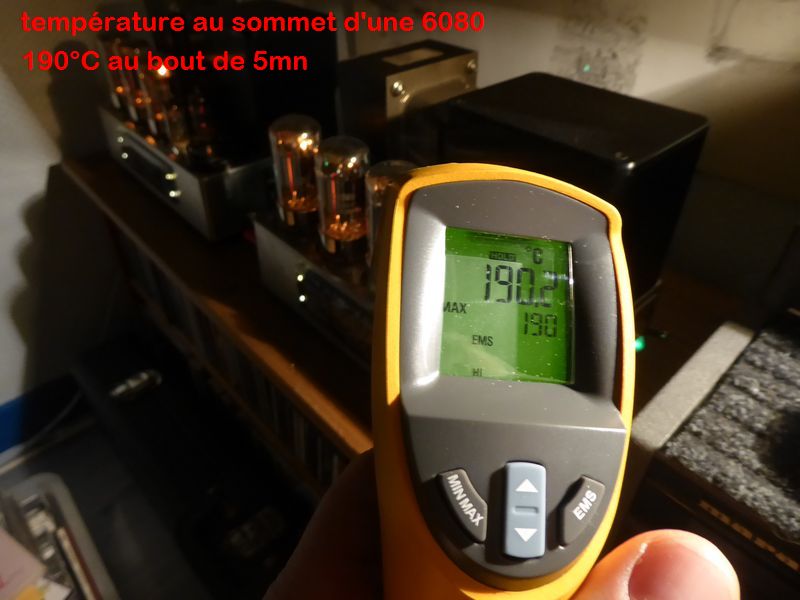
Translation : temperature at the top of a 6080WA tube, stabilized after 5mn of idle operation at 190°C.
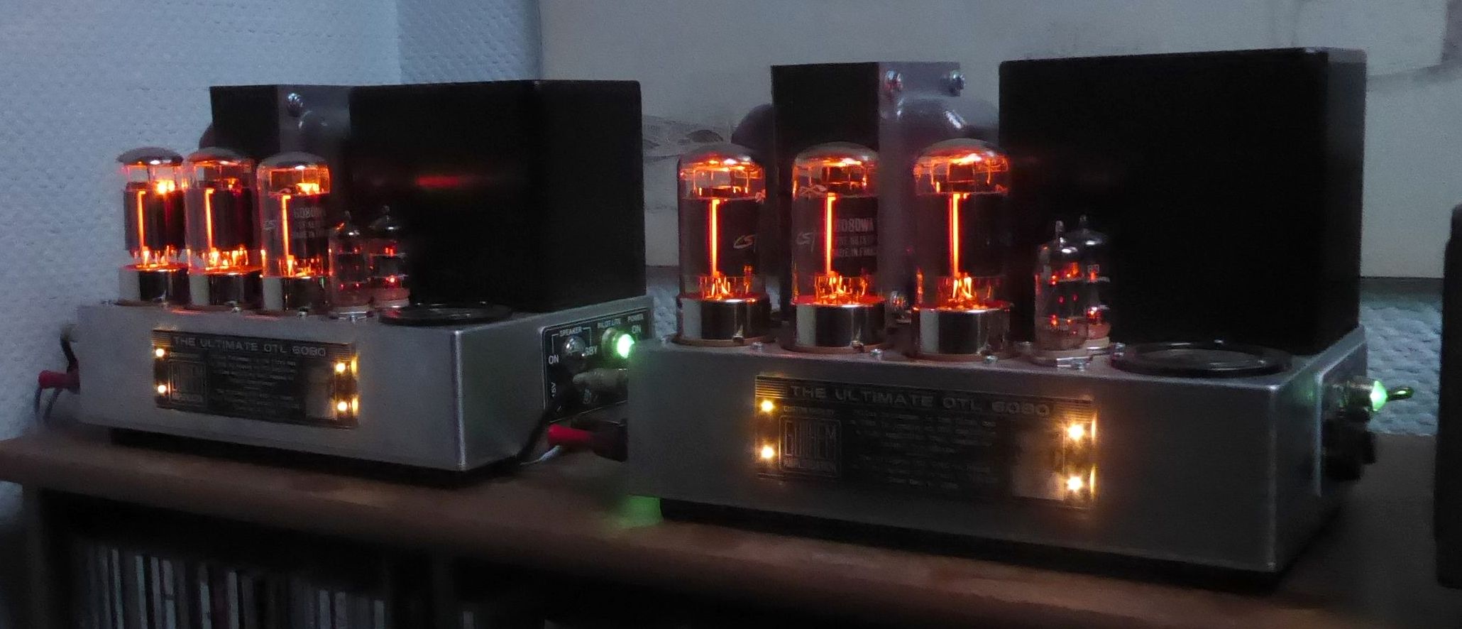
On this amp, I also use a some kind of forced chimney cooling :
A friend of mine - long ago, he has now passed away - designed and built a Class A MOS-FET amplifier (sorry, no pictures nor schematic available), it had a large A4 format heatsink at the top and nonetheless required a light forced inside ventilation by the back. But it was a 2x30W amp, IIRC not a 2x10W.
With power transistors operating in class A, if I sacrifice power output (and power supply hence), I will have also less heat - right ? Or am I dreaming ?
T
Last edited:
@ tubelectron
Here is the link to the hybrid amp as mentioned https://worldradiohistory.com/UK/Wireless-World/90s/Wireless-World-1991-08.pdf
You will have to scroll down past all the advertisements to page 676 to find the article.
Thanks @mjona ! Yes, that's true : there are a lot of Hybrid amps that have been developed with success since then...
Well, in my personal position, if I used tubes at the output stage of an amp, I would also use tubes for the preamp and driver stages too !
T
You seem to be a technical and meticulous person, I recommend that you read the original article by Mr hood, the article of 69.
I've probably said it many times but it's all in this article.
You mean this one @huggygood ?
T
- Home
- Amplifiers
- Solid State
- JLH 10 Watt class A amplifier