mjona- I assume by 500uF base modulation cap you mean a bootstrap? Unless the JLH circuit you referred to (page608) has a different configuration to the 1969 version. Which month was that?
In any case, the Calvert circuit is not a push-pull as you say and probably does not match the JLH distortion figures as a result.
In any case, the Calvert circuit is not a push-pull as you say and probably does not match the JLH distortion figures as a result.
Taking your points here first things are the same here. Reverse log taper C ones are a rarity here. Likely uses are for restoration of vintage valve / tube pre-amps.mjona- in the UK linear pots are A, log are B and reverse log are C.
Re your first message, the Wireless World issue for page 608 from December 1970, reference Fig 3, shows the voltage drop across the 0.5R resistor arranged to pass a.c. signal through the 500uF capacitor to
Tr2 base.
I have simulated this arrangement in The JLH1996 amp with some changes to align with Calvert's design - supply rails reduced to +/- 14V. The peak current and output voltage is slightly higher in this when the 500uF cap is in circuit than when it is out.
I did not go as far as reducing the values of the bias network resistors for Tr1 in my simulation re the Calvert circuit. It is what it is.
Re noise I agree wholly with your comment. As you have indicated that goes with high circuit impedance. In my domestic set up I use a 2k2 electric motor dual log pot with wireless remote control for volume adjustment.
Attachments
In conclusion:
Source: Maximum output level according to manufacturer (in to the preamp): 2.22 Vrms.
JLH class A power amp has correct gain, ~12.8.
Preamp buffers (in total 2 for each channel) gain is 1, measured before and after each buffer.
Signal level in to power amp at listening sound level: 66mVpp, (output from source: 2.35Vpp). Just instant “maximum” amplitude measurement.
Is this signallevel to the power amp ok? Low??
One suggested solution: Use a voltage divider or serieresistor before the input cap to the JLH Class A amp or even between source and preamp.
However, seems the major culprit is the volume control.
Potentiometer: Have a volume control when cranked right down making levels hard to set.
Used potentiometers: logarithmic Bourns, 91A2A-B24-D20/D20L, 20% Conductive Plastic potentiometer. 100kOhm, 1/4W, ±20%. (Have also tested with Bourns, 91A2A-B28-B20/B20L (linear) - Conductive Plastic potentiometer. 100kOhm, 1/2W, ±20 %).
A solution could be build my own stereo ladder stepped attenuator, using for instance Elma 4 pole 47 way switch, A47-SERB4-THT with well chosen resistor values….. fixing the problem with making levels hard to set when volume control cranked right down.
Any suggestions on switch?
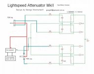
Sound wise, between the two buffers (gain=1) I prefer to use the lightspeed attenuator (a series/ shunt LDR arrangement) over the standard potentiometer. IMHO the lightspeed attenuator excels in transparency and dynamics of sound.
Source: Maximum output level according to manufacturer (in to the preamp): 2.22 Vrms.
JLH class A power amp has correct gain, ~12.8.
Preamp buffers (in total 2 for each channel) gain is 1, measured before and after each buffer.
Signal level in to power amp at listening sound level: 66mVpp, (output from source: 2.35Vpp). Just instant “maximum” amplitude measurement.
Is this signallevel to the power amp ok? Low??
One suggested solution: Use a voltage divider or serieresistor before the input cap to the JLH Class A amp or even between source and preamp.
However, seems the major culprit is the volume control.
Potentiometer: Have a volume control when cranked right down making levels hard to set.
Used potentiometers: logarithmic Bourns, 91A2A-B24-D20/D20L, 20% Conductive Plastic potentiometer. 100kOhm, 1/4W, ±20%. (Have also tested with Bourns, 91A2A-B28-B20/B20L (linear) - Conductive Plastic potentiometer. 100kOhm, 1/2W, ±20 %).
A solution could be build my own stereo ladder stepped attenuator, using for instance Elma 4 pole 47 way switch, A47-SERB4-THT with well chosen resistor values….. fixing the problem with making levels hard to set when volume control cranked right down.
Any suggestions on switch?
Sound wise, between the two buffers (gain=1) I prefer to use the lightspeed attenuator (a series/ shunt LDR arrangement) over the standard potentiometer. IMHO the lightspeed attenuator excels in transparency and dynamics of sound.
Attachments
It would help if you could recommend at least one.About 20 years ago I bought a two gang log taper manufactured by Bourns I will never buy one again.
mjona- thanks for the circuit reference. The 500uF holds the PNP BE voltage (more or less) constant and ensures it is mostly constant current. Not a bootstrap.
Though I was surprised that JLH recommended a transistor like the 2N4919 which is a slow epibase device. The 2N2905(A) was rated at 3W so a better choice may have been (back then) a 40362, 2N4033, or 2N4036 or today, a BD140.
Reverse log pots were indeed used in valve circuits usually in passive tone control circuits.
Not sure I could recommend a decent reasonably priced pot either. Many I've bought don't last long before getting noisy, but it is possible to service some of the older types.
Hello All !
I could not read all the 476 pages of the tread, sorry, but I am also interested to build a 2x10W John Linsley Hood Class A amplifier - from a kit :
https://www.audiophonics.fr/en/ampl...-a-amplifier-bipolar-2x10w-8-ohm-p-11617.html

My question is : would the radiator below be convenient for such a project ? The idea is to use it as the top of the amp, and install the four power transistors flat in contact (plus conductive paste) underneath, on the bottom of the radiator.
Here it is :

I am a noob about designing-building Solid State amps ... So thanks to let me know !
T
I could not read all the 476 pages of the tread, sorry, but I am also interested to build a 2x10W John Linsley Hood Class A amplifier - from a kit :
https://www.audiophonics.fr/en/ampl...-a-amplifier-bipolar-2x10w-8-ohm-p-11617.html
My question is : would the radiator below be convenient for such a project ? The idea is to use it as the top of the amp, and install the four power transistors flat in contact (plus conductive paste) underneath, on the bottom of the radiator.
Here it is :
I am a noob about designing-building Solid State amps
... So thanks to let me know ! T
From memory Nelson Pass recommended a low cost potentiometer for a power amp. It could have made by Alps.,You could enter search fields with his name and Alps to see what the engine brings up. Also you could look at some audiophile amp service manual from 1980It would help if you could recommend at least one.
on and check the component lists - copy the manufacturers part numbers and search those details. A query about your attenuator doecdthe output
@tubelectron
I have the same one lying around somewhere in the workshop and seen from here, I think your heatsink is too small.
I think it might do it but it's really just.
with the same problem as you, I ended up grafting it on a subwoofer heatsink.
I have the same one lying around somewhere in the workshop and seen from here, I think your heatsink is too small.
I think it might do it but it's really just.
with the same problem as you, I ended up grafting it on a subwoofer heatsink.
I see... Thanks @huggygood !
This heatsink comes from a 2x 200WRMS PA-Mixer, so I thought it would be enough with its 251x212mm surface for cooling four poor transistors in Class A placed in the center.
T
This heatsink comes from a 2x 200WRMS PA-Mixer, so I thought it would be enough with its 251x212mm surface for cooling four poor transistors in Class A placed in the center.
T
Area 3400 sq. cm is enough. It is advisable to arrange the fins vertically for better cooling.radiator
You will need insulated thermal pads under each transistor.
Use racks to mount the PСB.
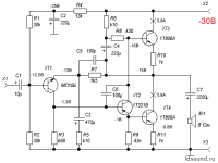
You can use the standard circuit and ready-made printed circuit boards. In this case, the polarity of the supply (ground (+)), the polarity of all electrolytes and the type of conductivity of all transistors.Any advice for the schematic of JLH with PNP output?
Attachments
Just where did I say that?What is clear that you think the latter is preferable.
Hood's own comments on the 220uf and his reasons for doing it also why he changed it in the 2023 circuitThe main difference in the cicuit submitted by A.H.Cavert is the omission of a 500uF base modulation cap between Tr2 emitter and base. The omission converts a push pull system into one that is single ended,
I still had some nagging doubts about the 1996 Iq control circuit and so I suggested introducing
another constant current source (Q7/Q8). As with the bootstrap circuit, the simulated distortion
figures were still half those for the 1996 version but with the added advantage that the distortion
did not increase at low frequencies due to a reduction in capacitor effectiveness. A further
advantage was an increase in amplifier efficiency (or maximum output). The maximum output
voltage swing with the ccs is greater than that for the standard 1996 circuit and the maximum
output current increases from around 1.35 to about 1.5 times the quiescent current.
Actually the LF distortion aspect somewhat depends on the gain of the top transistor - the place where he suggested putting the highest gain power transistor.
The Clavert design has i's features but is it suitable for a novice to build or even some of the posters on this thread. I'd say no.
In some ways yes as generally I would choose inverting.AjohnL - you seem to be confused between op-amp gains. In the non-inverting configuration the gain is set by (Rf+Rg)/Rg where Rf is the feedback resistor and Rg the one which goes to ground. In the inverting configuration the gain is (-)Rf/Rin.
In fact I can't recollect using a none inverting at work or at home with gain. From https://www.ti.com/lit/an/sboa092b/sboa092b.pdf Slap my legs. However I do realise that these sums are only correct in high gain op amp type situations.It looks easier than I thought.You can use the standard circuit and ready-made printed circuit boards. In this case, the polarity of the supply (ground (+)), the polarity of all electrolytes and the type of conductivity of all transistors.
Many thank !
- Home
- Amplifiers
- Solid State
- JLH 10 Watt class A amplifier