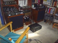
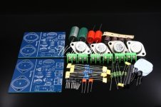
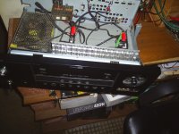
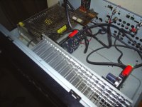
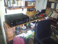
My JLH 1969 amp build before the pandemic
PSU: SMPS 24v 10A
Board: SC HOOD JLH 1969 Gold seal ST2N3055 10W+10W Class A Stereo Amplifier Kit (Ebay)
Chasis: (A Gift) A Old yamaha receiver RX-V 463 great heatsink
PSU: SMPS 24v 10A
Board: SC HOOD JLH 1969 Gold seal ST2N3055 10W+10W Class A Stereo Amplifier Kit (Ebay)
Chasis: (A Gift) A Old yamaha receiver RX-V 463 great heatsink
Attachments

If the output impedance of your buffer pre-amp is more than a few thousand Ohms there will be a mismatch between this and the Class A input impedance the usual with valve pre-amps at the time. That goes with the territory of high operating voltage and high resistor values in these circuits.
Does your user manual for your buffer say whether or not this is suitable for use with an amplifier having a BJT input .
There was a suggested modification to the JLH Class A amp for matcing valve pre-amps using a FET as a single stage buffer.
Does your user manual for your buffer say whether or not this is suitable for use with an amplifier having a BJT input .
There was a suggested modification to the JLH Class A amp for matcing valve pre-amps using a FET as a single stage buffer.
Attached is the general simulation file (in LTSpice IV) referred to in post 9459 - this set up to run at 1kHz at 1W output,
There are two results for THD the second of which is "normalized" a term which raised some questions see -
https://www.diyaudio.com/community/threads/ltspice-error-log-thd-values.269340 (a closed thread) for explanations.
Swapping out the 2N3094 for 2N5551 gives slightly better THD, the figure, not in brackets in the error log.
Attachments
Have JLH 2003 with a 2u2 input cap. I would like to decrease its input sensitivity. Plan to put a voltage divider to reduce output (and increase useable range on volume control).
Best placement of the voltage divider? Before input cap OR directly after input cap but before input filter (need then to adjust DC-level)?
Would fx 100k and 27k work or 15k and 2k7? Any suggestions on values? Rule of thumb, how to think?
Best placement of the voltage divider? Before input cap OR directly after input cap but before input filter (need then to adjust DC-level)?
Would fx 100k and 27k work or 15k and 2k7? Any suggestions on values? Rule of thumb, how to think?
Last edited:
You could try reducing the gain by increasing the value of R4 which sets the AC gain of the amp.I would like to decrease its input sensitivity. Plan to put a voltage divider to reduce output (and increase useable range on volume control).
The input impedance is ~100k//100k so 50k suggesting a buffer after the vol control might be the best answer.
That's the original circuit.
The 2003 version also has the ac gain set by a resistor to ground via a cap so same thing can be done. R6. The input impedance is again ~50k and forms a high pass filter via the input cap. A 50k in series with the input would reduce the gain by a factor if ~2 and still be AC coupled to the amp. Simple voltage divider. The gain of this version is ~R8/R6. Reducing it may add instability but on the other hand a greater feed fact factor tends to improve things.
All of the ~ ie aprox - joys of roughing out bipolar amps. You could throw in Ib and hfe but that may be more appropriate working back from the power output.
I built the 1996 amplifier one of the necessities for this is to boost the signal input for most sources ahead of the volume control.
A closed loop gain of 13 is barely enough for phono stages to reach a decent level of volume at maximum shaft rotation. Reducing the closed loop gain of the amplifier is not a solution.
If you click on the link in post 9468 and scroll down to the 1989 JLH Mosfet integrated amplifier, have a look-see how the signal feed in this is set up.
The power amp section has a closed loop gain of 26 twice that of the JLH Class A amp at 13.
That is largely due to the need to generate higher output voltages roughly double the Class A amp (15.5 vRMS versus 28.28vRMS). That puts the respective needs on a par level. In either situation a line amplifier with closed loop gain of 2 is a reasonable solution.
In viewing a log pot from the front with all legs pointing downward, that to, the leg to the left of the wiper in the middle should be soldered to earth, and, that to the right to the amplifier input. That would be normal with pcb layout to avoid ingress of airborne contaminants, dust and moisture reaching the wiper tracks. The wiper of course should connect to the input from the signal source.
Pots with log taper are marked by the letter A I'm taking that for granted that is what your have.
If the pot is not pcb mounted that raises a question of whether this is secured through a hole in the front panel with a nut and whether or not the legs of the pot point down or up. In the latter case you should check that the order of the legs of the pot have not been reversed by flipping and do not follow the order described in my third paragraph.
I suggest you check this and change the order if necessary and alter the orientation of the pot so the legs point downward.
It's a power amp not a pre amp. He did publish a modular pre amp design where each stage can be used on it's ownI built the 1996 amplifier one of the necessities for this is to boost the signal input for most sources ahead of the volume control.
https://keith-snook.info/wireless-world-articles/Wireless-World-1969/Modular Pre-amplifier Design-DCD.pdf
Eg just the vol and tone control section. Pity it uses a FET. It probably had well defined characteristics - mins and max's stated. If those can be found there will probably be an equivalent around.
A series resistor is the simplest as already has a volume control. It's value will also depend on the output impedance of his pre amp so trial values or a trimmer. I'd try trial values.Have JLH 2003 with a 2u2 input cap. I would like to decrease its input sensitivity. Plan to put a voltage divider to reduce output (and increase useable range on volume control).
Not sure about upload sizes on here but there is another pre amp design and modern op amps would give much better results but will need connecting correctly. Parts no problem - the strange transistor part numbers are plastic versions of metal canned BC108 etc. The magnetic input could be omitted and the vol control capacitively connected if needed.
If the upload doesn't work the pdf is in the first few pages of this link
https://worldradiohistory.com/UK/Wireless-World/70s/Wireless-World-1970-07.pdf
There was also one based on 741 op amps.
If the upload doesn't work the pdf is in the first few pages of this link
https://worldradiohistory.com/UK/Wireless-World/70s/Wireless-World-1970-07.pdf
There was also one based on 741 op amps.
Attachments
I did not build the JLH modular pre-amp from 1969 for which there was a postscript in Wireless World issue of December 1970. However I did build the Modular Pre-amp described in that journal in issues between October 1982 and November 1982 continued in January and February 1983. You can look these up in the link in your radio history.com post with amended dates.
If you look at the first page of the October 1982 issue you will see comment by JLH that much had changed in the demanding world of hi-fi since 1969 and much more was necessary than the kinds of circuit blocks which were merely a large improvement on a rather off-colour 1950 d.i.y hotch-potch.
That may be of historic interest to a few but not many would consider pursuing these circuit blocks.
Anyway my point was the problem in consideration is to do with the volume control and not the amplifier.
While a log taper pot has been used, Nico Ras spotted the possibility that this was not wired correctly.
From what I could see there were power amp kit pcb's alone and it was up to the builder to hard wire a volume control without one.
Unfortunately this left room for an error which the symptoms described suggest this has arisen.
I expect our member will come back with an answer on how wired when he is ready. Like other followers on this thread, polite enough to wait, so am I.
+1I expect our member will come back with an answer on how wired when he is ready. Like other followers on this thread, polite enough to wait, so am I.
A pot should always be wired so that the volume increases when turned clockwise. Thus, the grounded side is at the zero volume position. The input is on the opposite tag and the output on the centre tag. A log pot if wired correctly would have a slow increase in volume until about centre position, after which it would increase more rapidly. If you reverse wire the volume control, the exact opposite would occur, volume would increase rapidly and then almost nothing at all.
Some volume controls have a tap somewhere along the minimum to centre position, this is normally used for "loudness" correction. If yours has this tap do not use it. To make sure your pot is okay, turn it to minimum position and the centre tap and one tag would be near zero resistance, this is where ground goes. Does this help? Just to be clear, the volume centre tap goes to your JLH input point. The far outer or max resistance tap to the source output.
Thank you all for your much appreciated answers!
The input source to my preamp is either a cd-player och a streamer.
I do have buffers with gain=1 before and after the volume control. Have tried both 100k log pot (and linear) and built the Lightspeed Attenuator as described by georgehifi here at diyaudio. With pots, very sensitive (strong) at low part of the pot - eventhough log pot. With the Lightspeed, lowest sound is to strong/lound.
The pot has always been wired correctly.
Will first try series resistor (variable). Is this the same as impedance/resistance matching ?
Will later reduce the gain in the JLH Class A amp, if really necessary.
- Home
- Amplifiers
- Solid State
- JLH 10 Watt class A amplifier