I will concede that MJL3281A has a greater Hfe than MJL21194. A stability plot for this used in combination with a BD139 rather than the 2N1711 phase split will be stable as the BD139 has a lower fT than 2N1711.Well, I don't disagree. I've also posted, some time ago, that one instance of JLH I built with 3281A output devices needed a 33pF compensation capacitor to stabilise. I don't however, recommend JLH's proposal for compensation which he wrote about later using three additions. The 3281A or 5200 versions have given the lowest distortion of the circuits I have measured.
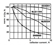
I'm not sure about your comment "similar current gains". The datasheets I have suggest that the 21194 gain has a minimum of 25 (typ. 50) compared to the 3281A at 75 (typ. 100). Though the 21194 could be better for low load impedances compared to earlier devices like the MJ480 or 2N3716. Since the JLH is a minimalist design, higher gains are beneficial, as JLH noted in his original article.
If the outputs are MJ15003 and used in combination with 2N1711 no additional capacitor is required for stability. I had considered using these for my build but opted for common 2N3055 epitaxials.
I will work up a simulation for MJL3281 Later. A point noted by JLH was the use of a Darlington MJ3001 in place of TR1 which would improve THD performance due to greater current gain.
Attachments
Naturally repeating the model of 1969 is a step to nowhere, it stands still, you need to move and develop the topology and quality.@Hennady Kovalsky, if you want supa lo THD and slew rate, JLH 10W is not for you.
Even the 2003 and 2005 models are a slightly improved version, but this is not enough.
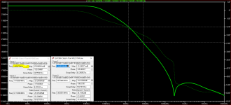
I got a similar distortion value, which is why I actually took up the modification. In the attachment, the version of my modification is much superior to the original version, while it has a greater output power and at least 10 times less distortion in the entire frequency band. By the modification itself, it can be seen that there are no significant changes in the signal flow in the topology, but the result is simply many times greater than the original.The distortion figures I reported (0.,15% at 20kHz) were using an 8 ohm load variant, and it gets worse still for the 4 ohm load.
Attachments
I'm not sure about your comment "similar current gains". The datasheets I have suggest that the 21194 gain has a minimum of 25 (typ. 50) compared to the 3281A at 75 (typ. 100). Though the 21194 could be better for low load impedances compared to earlier devices like the MJ480 or 2N3716.
if you erase the attachment, much becomes clear without words. it is very difficult to understand hams still using the 3055 in class A.
Attachments
Well, I don't disagree. I've also posted, some time ago, that one instance of JLH I built with 3281A output devices needed a 33pF compensation capacitor to stabilise.
indeed a 33pF capacitor in parallel with the 2.7kΩ Feedback resistor was shown in a JLH 2005 implementation paper on transistors 2SA970, 2SC3421, and two pairs of MJ15003.
I found my data on a modified version, with an output power of 31 watts (6 ohms) 0.048% (1 kHz and 20 kHz) only the 3rd harmonic. With an output power of 1 watt into a load of 6 ohms, distortion is 0.006% (1kHz and 20kHz) 2nd harmonic, 0.0015% (1kHz and 20kHz) 3rd harmonic. As you can see, the level of distortion did not depend on the frequency.I reported (0.,15% at 20kHz) were using an 8 ohm load variant,
P.S. for topology JLH, load with an impedance of 4 ohms is strictly contraindicated.
Wonderful idea!Naturally repeating the model of 1969 is a step to nowhere, it stands still, you need to move and develop the topology and quality.
Even the 2003 and 2005 models are a slightly improved version, but this is not enough.
I got a similar distortion value, which is why I actually took up the modification. In the attachment, the version of my modification is much superior to the original version, while it has a greater output power and at least 10 times less distortion in the entire frequency band. By the modification itself, it can be seen that there are no significant changes in the signal flow in the topology, but the result is simply many times greater than the original.
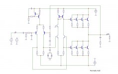
But all parrallelings of parts is difficult: exacter: I do not know a single one parralelling tha regards "current", "circuit", "all at ONE point" - all our engineers do not understand circuit, current;-)-;
The summing of parts, especially active parts (the differential amp, the "positive" feedback-loop and so on), brings the sound down. The MUST: hearing all transes before using. But my experience: 9 of 10 parts are unfit for audio! A lot of work I do see.
I was curious about the use of the Mj3001, because it changes the nature of the operation. Because the gain is higher, the distortion will be reduced, but the current flow into the base of the 3001 will be so low that the upper output device will hardly change, and act more as a constant current. That will reduce the efficiency even more than the original. I did not look into that further because of the imbalance, although the reduction in efficiency in a Class A design is generally not a big issue for Class A designs. Darlingtons also had a fairly poor SOA.I will concede that MJL3281A has a greater Hfe than MJL21194. A stability plot for this used in combination with a BD139 rather than the 2N1711 phase split will be stable as the BD139 has a lower fT than 2N1711.
If the outputs are MJ15003 and used in combination with 2N1711 no additional capacitor is required for stability. I had considered using these for my build but opted for common 2N3055 epitaxials.
I will work up a simulation for MJL3281 Later. A point noted by JLH was the use of a Darlington MJ3001 in place of TR1 which would improve THD performance due to greater current gain.
I have looked into the stability of the 3281 version, and suggest a slightly different arrangement for stabilising if putting a capacitor across the feedback resistor is considered inadvisable (Bob Cordell suggests this, though I have not foud any particular problems).
This is to use a version of the compensation technique used by Bailey, with a 100pF capacitor connected to the emitter of the PNP input device in series with 100 ohms connected to the driver collector, and accompanied with 47 ohm "sprog stopper" resistors in series with the 3281 bases. Tian plot I ran showed no 180 degree phase shift, but a gain increase and phase reduction beyond 100MHz due presumably to forward conduction through the transistors capacitances. Otherwise, phase margin and gain margin were 80 degrees and 30dB.
This is to use a version of the compensation technique used by Bailey, with a 100pF capacitor connected to the emitter of the PNP input device in series with 100 ohms connected to the driver collector, and accompanied with 47 ohm "sprog stopper" resistors in series with the 3281 bases. Tian plot I ran showed no 180 degree phase shift, but a gain increase and phase reduction beyond 100MHz due presumably to forward conduction through the transistors capacitances. Otherwise, phase margin and gain margin were 80 degrees and 30dB.
in the proposed modification, the diffcascade isolates the emitter from the electrolyte capacitance in the negative feedback circuit. There is no need to have a trained ear, as the electrolyte degrades the sound quality in the original JLH.The summing of parts, especially active parts (the differential amp, the "positive" feedback-loop and so on), brings the sound down.
I have a musical education, in my youth I played in an ensemble, all works projects are tested for listening, including blind ones - so the subjective opinion becomes more objective and really helps to determine successful topological solutions in power amplifiers.But my experience: 9 of 10 parts are unfit for audio! A lot of work I do see.
I'm not sure, either, about the ft of the BD139 being lower than the 2N1711.I will concede that MJL3281A has a greater Hfe than MJL21194. A stability plot for this used in combination with a BD139 rather than the 2N1711 phase split will be stable as the BD139 has a lower fT than 2N1711.
If the outputs are MJ15003 and used in combination with 2N1711 no additional capacitor is required for stability. I had considered using these for my build but opted for common 2N3055 epitaxials.
I will work up a simulation for MJL3281 Later. A point noted by JLH was the use of a Darlington MJ3001 in place of TR1 which would improve THD performance due to greater current gain.
Data sheets I have for the BD139 suggest an ft (typ) of 250MHz. For the 2N1711 all the datasheets I have (Philips/RCA) state fT 70MHz min. Typical devices of that era (2N1613) seem to have fT's of 100MHz, so my view is that they are all similar. There are however several variants of the BD139, but devices from Motorola (as they were) and ST measured gains of 100 at 1MHz when I checked. I don't have any 2N1711's to compare, but I don't see that JLH's assertion of 400MHz would be realistic. Maybe older datasheets with published characteristics would show that as a peak.
The BD139 has a higher Cjc (though this was omitted in early datasheets, but I have measured some at around 45pF) than the stated 2N1711 (25pF max). This could be the reason for better performance of the 2N1711 rather than fT as such.
I think Onsemi's BD139 is only spec.d at nominal Ft of 50MHz according to datasheets I located but I'm unsure whether theirs or Fairchild's version is still in production now. These are probably bettered by many Japanese TO126 and TO92L drivers, even typical Chinese copies of Hitachi's 2SD669A or 2SD667A types. Unisonic BD139 though, (marketed by Profusion) is spec.d higher, at 190MHz and seems a safer deal.
Also, there are some fair copies of 2SC2705/A1145 floating around the platform websites that might be worth a trial. The originals were 200 MHz - not sure what they are now but the 2SC2705 sample I checked just by listening, did sound rather good in my (typical kit version) JLH. If you prefer something well known here at DIYaudio, Onsemi's KSC3503 (150 MHz) seems OK and Toshiba still has TTC004 (100MHz) which may be worth checking. I suspect there are plenty of other small Japanese type driver/VAS transistors and copies of them that would be as good or perhaps better.
Also, there are some fair copies of 2SC2705/A1145 floating around the platform websites that might be worth a trial. The originals were 200 MHz - not sure what they are now but the 2SC2705 sample I checked just by listening, did sound rather good in my (typical kit version) JLH. If you prefer something well known here at DIYaudio, Onsemi's KSC3503 (150 MHz) seems OK and Toshiba still has TTC004 (100MHz) which may be worth checking. I suspect there are plenty of other small Japanese type driver/VAS transistors and copies of them that would be as good or perhaps better.
Last edited:
Go back to my old posts, I tested almost 40 transistors instead of 2N1711.
And the winner is definitely 2SC1941, next is 2SC2682, then KSC3505, 2SC2705(2SC3432) and 2SC3611.(all with high hfe)
The BD139 that I tested was the original Philips and they are not bad if I compare them with the new production.
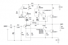
The output is 80MHz, 2SC3284-Y, and the compensation of 4.7pF is only needed with 2SC2682. The amplifier is stable and sounds better than a couple of Pass amplifiers with which I made a comparison.
And the winner is definitely 2SC1941, next is 2SC2682, then KSC3505, 2SC2705(2SC3432) and 2SC3611.(all with high hfe)
The BD139 that I tested was the original Philips and they are not bad if I compare them with the new production.
The output is 80MHz, 2SC3284-Y, and the compensation of 4.7pF is only needed with 2SC2682. The amplifier is stable and sounds better than a couple of Pass amplifiers with which I made a comparison.
Attachments
Re: # 8554
Yes, as suggested in #8552. However, part reference numbers are not enough to identify what you actually tested, particularly if your source is a platform seller like Aliexpress, Ebay, Amazon etc. I learned this the hard way and wasted many hours with parts that looked promising but proved to be different from one lot to the next. Lots looked identical to each other but they were not identified with any particular manufacturer or source codes that would allow them to be traceable. So, next time I bought some, they were different spec. transistors yet all had the same markings!
Yes, as suggested in #8552. However, part reference numbers are not enough to identify what you actually tested, particularly if your source is a platform seller like Aliexpress, Ebay, Amazon etc. I learned this the hard way and wasted many hours with parts that looked promising but proved to be different from one lot to the next. Lots looked identical to each other but they were not identified with any particular manufacturer or source codes that would allow them to be traceable. So, next time I bought some, they were different spec. transistors yet all had the same markings!
Last edited:
Member
Joined 2009
Paid Member
Actually, if it's of interest, I did parallel parts to improve the current handling. In fact, I think I hold the world record for the number of output transistors on a JLH69 amplifier...But all parrallelings of parts is difficult: exacter: I do not know a single one parralelling tha regards "current"...

https://www.diyaudio.com/community/threads/tgm9-my-version-of-the-jlh-69-class-a-amplifier.268846/
;-)Actually, if it's of interest, I did parallel parts to improve the current handling. In fact, I think I hold the world record for the number of output transistors on a JLH69 amplifier
https://www.diyaudio.com/community/threads/tgm9-my-version-of-the-jlh-69-class-a-amplifier.268846/
Just discovered.
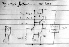
I would continue this path. For instance Tr1, Tr2, Tr3: any others in TO-126. I would try a lot of transes: these do sound very very different, 9 of 10 are unusable for audio;-)-;
Remove the bootstrap C and put R1 and R2 together.
Trimmer between output and base Tr3.
10 - 20 V supply will do.
You could use as follower, as 1 step amp, as 2 step amp.
I prefer the 1 step amp most.
Attachments
Member
Joined 2009
Paid Member
- Home
- Amplifiers
- Solid State
- JLH 10 Watt class A amplifier