yes, in own designs, i make connectors RCA side by side, but the JLH 1969 amplifier is not of the quality level where such a bug will be noticeable when listening to audio.connect the double-mono-psus together, first.
Are you generally aware: firstly, about the value of the slew rate of this amplifier?
Secondly: its capabilities when working on a load with a capacitive impedance?
The location of the RCA connectors is the last thing you can pay attention to in this amplifier JLH.
This amplifier operates in Class A the transistors do not turn off so there is no slew rate issue such as can exist with a LTP front end with a dominant pole capacitor strung between the collector and base of the Vas transistor.yes, in own designs, i make connectors RCA side by side, but the JLH 1969 amplifier is not of the quality level where such a bug will be noticeable when listening to audio.
Are you generally aware: firstly, about the value of the slew rate of this amplifier?
Secondly: its capabilities when working on a load with a capacitive impedance?
The location of the RCA connectors is the last thing you can pay attention to in this amplifier JLH.
There is no LTP stage or dominant pole capacitor in the circuit so the Vas transistor cannot amplify the value of dominant pole capacitor and dump the load at the base of the Vas transistor.
The dumped load varies depending on the voltage seen at the collector of the Vas transistor so the LTP is presented with a non-linear load needing to be driven at the base of the Vas transistor.
Better LTP designs include a buffer transistor stage ahead of the Vas and take the dominant pole from the collector of the Vas to the base of the buffer.
The difficulty with this is the arrangement has biasing issues when applied to a design which uses a single input transistor. I have commented on this today in another current thread.
No-one has come out in support of your comments so you stand alone on this platform. It is not hard to understand why.
This amplifier operates in Class A the transistors do not turn off so there is no slew rate issue such as can exist with a LTP front end with a dominant pole capacitor strung between the collector and base of the Vas transistor.
the fact that you do not understand this issue does not mean at all that this amplifier has no problems with the slew rate, and the class of the amplifier has nothing to do with it.
Better LTP designs include a buffer transistor stage ahead of the Vas and take the dominant pole from the collector of the Vas to the base of the buffer.
do not write nonsense, an important task is the linearity of amplification up to coverage by a common negative feedback, I will not write about the reasons, maybe someday you will guess ...
wrong again)))..No-one has come out in support of your comments so you stand alone on this platform. It is not hard to understand why.

The JLH is one of the finest and most versatile designs, in my mind;-)
Some key tips:
Some key tips:
- remove the "bootstrap"-C - does not run half-wave-symmetrical anyway
- do not use the complete circuit: just set the input at T1 or T2 or T3 (original schema) - per cap.
- do not use TO-3- transistors, and no TO-3P, MT-200, TO-247, SOT-227... the big ones;-)
- T1, T2, T3 the same type
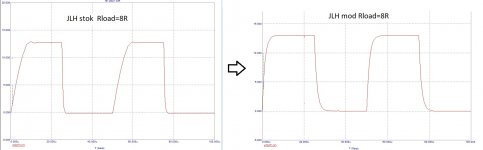
The image shows rise time and settling time - you did not include a cursor for the latter.It is better to see once, in the attachment of the meander of the stock and modified versions, the current of the power transistors is the same, the sensitivity is the same, the load is the same, only modification is necessary to get a modern sound.
If you had done this you would have seen the time difference between these points equates to a frequency of 20kHz at high power output for the whole amplifier. If there was a slew rate issue due to the Vas stage as you have inferred that would not have been possible.
See attached image for 15 volts peak into 8R - bottom left hand corner of Diff time 50uS and frequency 20kHz horizontal cursor 2-cursor1. The small deviation in these results is due to dc offset of 6 mV.
Attachments
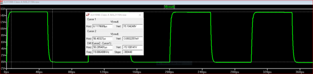
do not write nonsense, the settings are the same for both versions of the circuits.The image shows rise time and settling time - you did not include a cursor for the latter.
Seriously? did I assume something to the Vas stage?If there was a slew rate issue due to the Vas stage as you have inferred that would not have been possible.
you seem to have deviations from understanding the essence of the process.The small deviation in these results
It was assembled of in fact 4 options the JLH, the reason for the modifications is the insufficient quality of sound reproduction on the reference acoustic systems. The meander was looked at on an osfilograph, the shape of which corresponded to what was in the simulator without any "cursors", and only from the 4th modification did the sound become more / less decent. further modification required a complete redesign of both the topology and the printed circuit board - no one agreed to finance this work, because. there are more versatile and much better subjective sounding schemes.
P.S. First step to class A? - ok, move on...
I'm more interested in other projects.
 The members of this thread are reminded of forum rule number 1.
 mjona - although you mention "This amplifier operates in Class A the transistors do not turn off so there is no slew rate issue such as can exist with a LTP front end" , I have posted many posts ago (probably somewhere around 4,000 IIRC) a comparison of slewing in the output stage which arises because of the limited fT of the output devices. Admittedly this was through simulation, but measurements using the original 2N3055 RCA device (ft=800kHz) and a 2N3716 (ft~4MHz) have confirmed that the results show a similar response as Hennady's rise times in that the rising edge is slower than the falling edge, especially on the original 2N3055. The fastest slew I showed was with modern devices like the MJL3281A/ 2SC5200. Just because slew isn't happening in the VAS does not mean it cannot arise in the output devices. I suspect you mean that slewing won't arise at 20kHz, but a square wave will reveal it (especially a 20kHz one with no input filter).
I would recommend faster devices especially for the JLH as they also provide another benefit with a more linear gain.
I would recommend faster devices especially for the JLH as they also provide another benefit with a more linear gain.
Mjona- in reply to your earlier post (8,500) I was specifically discussing distortion at higher output levels, not due to Early effect in the VAS, but due to gain non-linearity in the output stages.
I have measured low distortion figures up to 20kHz as you say, but at low powers. At higher output powers (10W but not clipping limited) the distortion increased typically to 0.15% with 2N3716 (4MHz) samples I have used, at 20kHz. Several effects contribute: not only gain non-linearity but near clipping, the gain falls additionally due to quasi-saturation. As a side-note, the original 2N3055 did not exhibit quasi saturation to anywhere near the same extent as epi base devices. Distortion can be reduced if the power supply voltages are raised to compensate, which also has the effect of reducing the collector-base capacitance and associated Early effec in the VAS, but there is still a significant swing (i.e. distortion) in value that choosing a high Early voltage transistor is still worth while.
I have measured low distortion figures up to 20kHz as you say, but at low powers. At higher output powers (10W but not clipping limited) the distortion increased typically to 0.15% with 2N3716 (4MHz) samples I have used, at 20kHz. Several effects contribute: not only gain non-linearity but near clipping, the gain falls additionally due to quasi-saturation. As a side-note, the original 2N3055 did not exhibit quasi saturation to anywhere near the same extent as epi base devices. Distortion can be reduced if the power supply voltages are raised to compensate, which also has the effect of reducing the collector-base capacitance and associated Early effec in the VAS, but there is still a significant swing (i.e. distortion) in value that choosing a high Early voltage transistor is still worth while.
How does a stable current source instead of a bootstrap change the Early effect?Any, even the simplest simulator without complex scientific research, makes it clear that the best transistor in a cascade VAS is a composite assembly of 2, 3, 4, and even 5 transistors. Quality grows from quantity in a logarithmic relationship. However, for a decade now, the selection of components for such a simple solution has been going on, and It looks more like a sporting interest.
A stable current source instead of a bootstrap circuit solves this problem.
What I think you mean is that a cascode pair will reduce Early effect distortion, but whether loaded by a constant current source or bootstrap is not significant. A CCS has another advantage over a bootstrap though.
Another point to note is that JLH (I too have the High Fidelity Designs publication and probably the original Wirelss WOrld articles in the loft) showed typical performance oscillograms with 15 ohm loads. I read that to mean his distortion graphs were also for the 15 ohm version too. The distortion figures I reported (0.,15% at 20kHz) were using an 8 ohm load variant, and it gets worse still for the 4 ohm load.
High gain transistors like MJL3281A would probably fare better at the lower load impedances.
High gain transistors like MJL3281A would probably fare better at the lower load impedances.
Hennady Kovalsky, if you want supa lo THD and slew rate, JLH 10W is not for you. But if you conduct DBLTs on it, you will find for some reason thought it has high THD, it is one of the few amps (actually ONLY amp) that is PREFERRED to a good supa lo THD, zillion V/us 'modern' amps. I know this from nearly 2 decades of DBLTs ... caveats about not overloading bla bla.
However, MANY Golden Pinnae amps (including by famous names on this forum) are unstable on real speaker loads, have serious xover at times which aren't picked up in da standard tests, misbehave when overloaded bla bla You can tell these from good 'modern amps' in DBLTs but they are NOT preferred.I think this is cos JLH 10W THD profile is quite unique and very similar to the last of the great Valve amplifiers. I would very much like a big amp with the same THD profile but Class B so it doesn't act as a space heater.
In his book Valve&Transistor Audio Amplifiers in a chapter on early Solid State Audio Amplifier Designs in remarks about his 10 Watt Class A design JLH observed "Because the transition frequency of the output transistors is of the order of 4MHz, whereas those of Q3 and Q4 are in the 400MHz range*, the circuit has an in-built dominant lag in it's loop phase angle NFB characteristics. This ensures the loop gain has fallen below unity before the loop phase angle reaches 180 degrees. No additional HF compensation networks are therefore necessary to ensure complete loop stability, even with reactive loads."
If 30 MHz transistors are used to replace 4MHz types such as MJL21194, which are noted for their linear characteristics and have similar current gain to MJL3281A, that will erode the stability margins as the dominant pole of these latter 30 MHz types will arise at a frequency several times higher. To maintain the same dominant pole to achieve the same starting point of MJL21194 for stability margin, an additional compensation network will be required.
* purportedly, one could select devices for these designations with fT quite a lot lower than 2N1711, 2N3906, and try these with MJL3281A
JLH had built the classic Williamson valve amplifier when KT66 valves became available for domestic consumption after the end of World War 2. An element in this circuit was a split load valve driving a pair of high power output valves in a form of Class A mode. JLH adopted this principle for his 1969 transistor Class A design.Hennady Kovalsky, if you want supa lo THD and slew rate, JLH 10W is not for you. But if you conduct DBLTs on it, you will find for some reason thought it has high THD, it is one of the few amps (actually ONLY amp) that is PREFERRED to a good supa lo THD, zillion V/us 'modern' amps. I know this from nearly 2 decades of DBLTs ... caveats about not overloading bla bla.
However, MANY Golden Pinnae amps (including by famous names on this forum) are unstable on real speaker loads, have serious xover at times which aren't picked up in da standard tests, misbehave when overloaded bla bla You can tell these from good 'modern amps' in DBLTs but they are NOT preferred.
I think this is cos JLH 10W THD profile is quite unique and very similar to the last of the great Valve amplifiers. I would very much like a big amp with the same THD profile but Class B so it doesn't act as a space heater.
Well, I don't disagree. I've also posted, some time ago, that one instance of JLH I built with 3281A output devices needed a 33pF compensation capacitor to stabilise. I don't however, recommend JLH's proposal for compensation which he wrote about later using three additions. The 3281A or 5200 versions have given the lowest distortion of the circuits I have measured.In his book Valve&Transistor Audio Amplifiers in a chapter on early Solid State Audio Amplifier Designs in remarks about his 10 Watt Class A design JLH observed "Because the transition frequency of the output transistors is of the order of 4MHz, whereas those of Q3 and Q4 are in the 400MHz range*, the circuit has an in-built dominant lag in it's loop phase angle NFB characteristics. This ensures the loop gain has fallen below unity before the loop phase angle reaches 180 degrees. No additional HF compensation networks are therefore necessary to ensure complete loop stability, even with reactive loads."
If 30 MHz transistors are used to replace 4MHz types such as MJL21194, which are noted for their linear characteristics and have similar current gain to MJL3281A, that will erode the stability margins as the dominant pole of these latter 30 MHz types will arise at a frequency several times higher. To maintain the same dominant pole to achieve the same starting point of MJL21194 for stability margin, an additional compensation network will be required.
* purportedly, one could select devices for these designations with fT quite a lot lower than 2N1711, 2N3906, and try these with MJL3281A
I'm not sure about your comment "similar current gains". The datasheets I have suggest that the 21194 gain has a minimum of 25 (typ. 50) compared to the 3281A at 75 (typ. 100). Though the 21194 could be better for low load impedances compared to earlier devices like the MJ480 or 2N3716. Since the JLH is a minimalist design, higher gains are beneficial, as JLH noted in his original article.
This is something I don't understand about public forums. Why do people who openly express no interest in a particular topic feel the need to haunt it with their opinions?- ok, move on...
I'm more interested in other projects.
Pls take your own advice and move on.
Thank you very much for this information... one instance of JLH I built with 3281A output devices needed a 33pF compensation capacitor to stabilise...
I have built a Geoff Moss's JLH-2005 version with MJ15003G at the output and would like to replace the output devices with ML2381A. Where should I locate the compensation capacitor?
In that instance I wired it in parallel with the feedback resistor. That has to come with a caution, since capacitors connected to the output can allow RF signals into the circuit. I'm not sure whether it would be as simple in the 2005 version, though, as I've not looked into that.
- Home
- Amplifiers
- Solid State
- JLH 10 Watt class A amplifier