By increasing voltage and current, you increase the output (and heat dissipated) power.
At power close to the maximum, asymmetry of the arms appears (different output impedances).
For OTL amplifiers with an output capacitor, it is recommended to set the operating point to achieve symmetry near the upper cutoff. Or by minimizing distortion near the cutoff. Or at the maximum output power . You have to choose")
Some excessive voltage (to the calculated) takes into account the real amplification characteristics (quasi-saturation) of the BJT.
At power close to the maximum, asymmetry of the arms appears (different output impedances).
For OTL amplifiers with an output capacitor, it is recommended to set the operating point to achieve symmetry near the upper cutoff. Or by minimizing distortion near the cutoff. Or at the maximum output power . You have to choose
Some excessive voltage (to the calculated) takes into account the real amplification characteristics (quasi-saturation) of the BJT.
Last edited:
An externally hosted image should be here but it was not working when we last tested it.
Output Transformerless AmplifiersYou really are!
Last edited:
So what's the efficiency of your speakers?But the reason I'm building headroom into the system is precisely to *not* operate close to clipping.
Somewhere in my archives (yes, I know) there's a reasoned assertion that to reproduce a pair of high heals on a wooden floor without clipping needs 500W into mid-80db/w speakers.
The implications are that your amplifier will clip, the question is: how ugly is it when it clips.
Way back in this thread I postulated that the lack of a differential input amp is a significant part of the "nice" sound of the JLH. What I'm not sure of is whether this is just the loop gain reduction (and therefore the reduction in fugly on clipping) or due to less diff amp distortion artefacts.
I quoted that to Robin Marshall once. He said it was complete nonsense as it was he who said it. It was BBC LS3/5a when he was at the BBC. His version the Audiomaster is highly respected. Meridian 105 suited them well. My dads 25 watt Kenwood receiver and some Audiomasters 3/5 can go quite loud.
So what's the efficiency of your speakers?
They're not speakers, they're xfmr-coupled electrostatic headphones. Described a couple pages back.
When describing the op amp version some differences may not be obvious. It's a Class A + AB. Lets say 100mA in A and whatever in AB. This makes the heat-sink much smaller. The gamble is by the time it becomes AB it's already very loud. This should keep hum low.
The op amp having first class power supply rejection should offer a bonus which might allow a simple rectifier capacitor power supply. Because it is eventually class AB it might even sound better!!!! It's judging how much class A. 3 Vrms should be OK.
It won't mimic a JLH or Hiraga ideal design. It is a near zero distortion option . The double feedback loop to encourage stability.
A design like this should drive speakers also and sound good. 7W rms 8R at a guess.
Ah, found it.They're not speakers, they're xfmr-coupled electrostatic headphones. Described a couple pages back.
JLH 10 Watt class A amplifier
Ok, Stax need about 5w (see here) The Stax SRA-12S draws 25W (stereo class A) so similar power.
So I don't think you're going to get away with much less than the standard 10W (3db above 5W) so I'd be concentrating on getting noise out of the system. Putting your PS in a separate box is an effective and well trodden path. Choke input PS with shunt regulation would be the next step
Ok, Stax need about 5w (see here) The Stax SRA-12S draws 25W (stereo class A) so similar power.It's not a Stax.
So I don't think you're going to get away with much less than the standard 10W (3db above 5W)
The 5W target includes the desired headroom. No worries, the situation is well in hand.
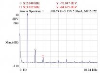
I tested 6 different sets of output transistors in the amp, all with Hfe of 60 to 125 and matched with an M328 tester. The three different sets of RCA 2N3055's from 1981 thru 1989 were all slow, risetime of ~1V/uS in the circuit. Seeing this, I would avoid RCA 3055's in the JLH. A Signetics NPN from a power supply was really slow, 0.2V/uS. A set of Motorola late-80's NPN's from an ACDC electronic load (house part numbers) were much better, distortion was low (H2 -79dBr), risetime 2.5V/uS. Probably would be fine for this low-power application.
But the winner was mid-90's Motorola MJ15022's. Fast (5-6V/uS) and the best distortion yet (H2 @ -80dBr), even with with 15V 500mA bias. See attached. With 18V 900mA bias, distortion came down another 2-3 dB.
I'll run with these, and do listening tests to see if the higher bias sounds significantly better to warrant using it.
Attachments
Last edited:
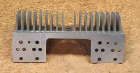
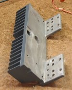
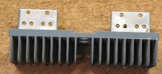
I thought this might be of general interest. I'm considering using this heatsink, scavenged from an old HP/Harrison 6205B power supply. 2 lbs of cast aluminum with holes for two sets of TO-3's. Holes in the center for power cord and fuse holder. Size 8"W x 3"H x 2" fins.
Except for the 6209B, these old 6200-series supplies are not in demand and can usually be had for next to nothing. Some models are twice as high. Looks like a great heatsink for JLH69 amps.
Except for the 6209B, these old 6200-series supplies are not in demand and can usually be had for next to nothing. Some models are twice as high. Looks like a great heatsink for JLH69 amps.
Attachments
Last edited:
Nice find! You need around 0.5K/W heatsink rating per channel to be comfortable around the original JLH's 10-15W version and two of these look to be just about right. From an earlier post, each channel dissipates around 36W constant which is quite significant.
Last edited:
MJ15022 with collector current from 0.2A to 3A has good linearity of gain and low saturation voltage. Ft=4mHz
https://static.chipdip.ru/lib/638/DOC005638922.pdf
https://static.chipdip.ru/lib/638/DOC005638922.pdf
Last edited:
Kin Let's add a circuit with an input transformer with separate windings.
Транзистор - усилитель. ч9
Let's add a circuit with an input transformer with separate windings.Транзистор - усилитель. ч9
http://www.farnell.com/datasheets/316951.pdf
2SC2500 is a common low capacitance device. Have a scope available to be sure a JLH will accept it. A simple square wave test says plenty. A 74HC4060 and crystal should give you cheap excellent square waves ( volume pot required , 10 K ? Decouple close to the chip for best purity as per spec sheet ). A 10 MHz scope is good enough for this. From my own tests this is the simplest way to test a JLH. I had to add a small cap ( 33 pF ) to the driver splitter.
To my mind the JLH shouldn't work. By choosing the output devices with care it does. It's a compromise between being able to drive at high frequencies ( > 10 kHz ) and being stable in both voltage and current domain with the real load.
I imagine Stax needs volts more than current. I have some somewhere. I suspect 100 mA to be enough.
#7796 To my mind the JLH shouldn't work. - #7794 Транзистор - усилитель. ч9
Circuitry of a sequential push-pull output stage with antiphase excitation was the standard in the 50s and 60s.
A quasi-complementary cascade is used in our time - another phase splitter circuit (npn / pnp). Similar topology
Circuitry of a sequential push-pull output stage with antiphase excitation was the standard in the 50s and 60s.
A quasi-complementary cascade is used in our time - another phase splitter circuit (npn / pnp). Similar topology
Last edited:
There was a lot of debate about that. It was argued people didn't understand transistors very well so persisted with hopeless designs. If class AB this likely is true. In class A magically it's not so bad. The driver splitter has a lot of work to do in the JLH. It's not like a valve phase splitter for simplicity. They in themselves are fascinating. Dynaco A70 I really like on paper, Direct coupled pentode to triode concertina. If teaching valve design it's my favourite. The JLH looks to be as inspired as the Dynaco which seems to be a RCA design.
Dear Nigel! Very similar, but in terms of power - Dinaco is better
Dynaco Stereo 70 II power amplifier Measurements | Stereophile.com
Dynaco Stereo 70 II power amplifier Measurements | Stereophile.com
As a very pure concept yes. UL feedback is complex. I find the A70 a little soft which I suspect could be improved. Marantz 9 isn't soft. Same output tubes. The 9 is a Williamson clone ( Sid said that to me }. He meant transformer type. JLH tried to clone his Williamson.
This is my favourite technical advisor. Well worth a read as what is said is universal for this circuit.
The Valve Wizard
This is my favourite technical advisor. Well worth a read as what is said is universal for this circuit.
The Valve Wizard
MJ15022 with collector current from 0.2A to 3A has good linearity of gain and low saturation voltage. Ft=4mHz
That is exactly what made me look at the transistors from electronic loads. I realized, the design of one pretty much requires (or is simplified with) load transistors having good current gain linearity. The remaining question was, are they fast enuf?
- Home
- Amplifiers
- Solid State
- JLH 10 Watt class A amplifier