Well my test bench signal source consists of a Sony CDP-CA70ES but then an Alps RK27 50k potentiometer before the amplifiers. The RK27 wiper is typically around 5k Ohms.
I do not have a buffer after the Alps RK27. Is this is a mistake with a JLH?
I am not using a pre-amplifier or buffer before the amplifier. Should I try to make a simple discrete Class A JFET buffer?
Hood wrote in the original article about using a pre-amplifier with an output impedance of no more than a few kilo-ohms. He never suggested using a potentiometer at the amplifier input.
#7741 Reduce the 5 ohm current supply resistor and increase the size of the heatsinks. The current (power) will increase. The details allow it (BJT).
Short the 20 ohm resistor at the output (after the capacitor).
...Lambda modular 24V supplies - Look at the source output with the oscilloscope input closed (through the capacitor) through a 1:10 divider.
Short the 20 ohm resistor at the output (after the capacitor).
...Lambda modular 24V supplies - Look at the source output with the oscilloscope input closed (through the capacitor) through a 1:10 divider.
Last edited:
I have a bunch of 2N3055 and MJ15022 outputs for these, and I'm going through testing them. The 15022's are all Motorola with Hfe from 30 to 70. The 3055's are from numerous sources, with date codes from mid-70's to mid-90's, with Hfe's from 7 to 300. The question is, when was the transition from hometaxial to epitaxial production? I assume it varied by manufacturer. Was there a certain date by which one can rely on them all being epi's ?
Nobody knows how many different chip manufacturers were from which different TO-3 devices were assembled, marked as 2n3055 (compliance with the 2n3055 specification). If the BJT is marked as 2n3055, measured as 2n3055, it works like 2n3055, it is highly likely 2n3055
")
2N3055 - Wikipedia
There is a proposal to test pairs of transistors on a real signal in a 3-BJT circuit from Hood's 1969 article (Without GNFB).
Last edited:
US3246251A (1963) is almost full 4-transistor JLH.Hi all! I'm interested who and when invented a 3-transistor combination = JLH without first transistor. Smb help?
Nobody knows how many different chip manufacturers were from which different TO-3 devices were assembled, marked as 2n3055 (compliance with the 2n3055 specification). If the BJT is marked as 2n3055, measured as 2n3055, it works like 2n3055, it is highly likely 2n3055
2N3055 - Wikipedia
I have read that page, and it is what prompted my question. Most of the 3055's I have are old Mot, RCA, and STM. I guess what I was hoping for is a simple go/nogo criteria by which to screen out the devices that were likely to be from the old process, without having to extensively test them all. For example, if the Wiki page is correct, then all RCA's after 1977 are the new process. All the STM's I have are from the 90's. I guess the uncertainty is the Motorola ones from the 1970's. At a certain point they labeled the slower, old process units with a letter suffix ("H", I believe). But when was it? I have one "H" unit and it measures very low Hfe on the M328 tester.
There is some discussion of this in this thread, starting on p.4:
sublimed JLH1969
But it stops short of identifying a specific point in time.
#7749 " I have one "H" unit" - Use as reference for measurements. 2n3055 have different chips, different internal design, different versions of the TO-3 package. General only compliance with specifications 2n3055 (no worse). For use in power units, they became less suitable after changing the technical process. We tried to use 2n3773.
Last edited:
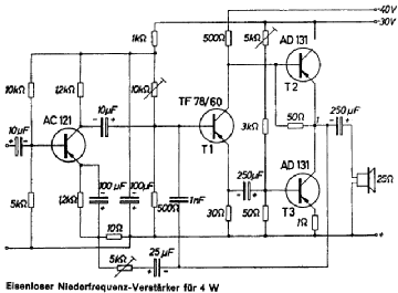
# 7447 Dear manufacturer of tape recorders (Ponyatov). Transistors pnp Ge, voltage gain 1. Works on the line. There is no bootstrap.
Lamp analogue of US2777020.
Scheme for Ge BJT. Used in Europe.
AD131: Siemens Halbleiter Schaltbeispiele April 1962
Günter Kudicke
Lamp analogue of US2777020.
Scheme for Ge BJT. Used in Europe.
AD131: Siemens Halbleiter Schaltbeispiele April 1962
Günter Kudicke
Last edited:
1.US3023368A - Direct coupled transistor amplifier#7746 schematic is exactly what I mean.
- Google Patents
US2943266A - Transistor amplifier circuit
- Google Patents
2.Construire Diverte 1967 12 s.930-937 DI H.Schreiber Amplificato...
5 BJT (2 discrete Darlingtons) 5-25W class AB.
The same scheme
Costruire diverte - Introni.itwww.introni.it › pdf › Costruire diverte 1967_12
Costruire diverte 1967_12.pdf - Google Search
Last edited:
US3418590A - Single ended push-pull class b amplifier with feedback
- Google Patents 1964-07-11
Priority to NL6407942A

- Google Patents 1964-07-11
Priority to NL6407942A
Last edited:

You really are!@OldDIY, you are a living encyclopedia!
Built the first amp and tested it. With a 15V rail @ 500mA idle current into 20 Ohm load, output is good for 5.1VRMS before visible clipping occurs. That's just about right level-wise for driving these phones, but doesn't leave any headroom. I may have to bump up the supply voltage a bit. Which would be a drag, because heat dissipation is quite manageable right now. Freq response is -3dB ~300kHz, but the waveform gets pretty asymmetrical and ugly from ~140kHz. Will test it for distortion later.
An op amp with booster transistors is another way. 7 Vrms is possible. I used two feedback loops so as to have some feedback directly to the op amp. OPA604 at the time
A class AB output can be made class A up to loud enough. It then becomes AB after that. This keeps hum low as music will mask it when we distort. If the outputs have high current gain the op amp will work in class A. This could sound better.Ears clip.
A class AB output can be made class A up to loud enough. It then becomes AB after that. This keeps hum low as music will mask it when we distort. If the outputs have high current gain the op amp will work in class A. This could sound better.Ears clip.
Last edited:
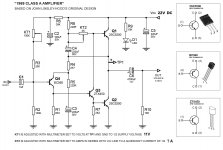
JLH 1969 10W (22V DC) IQ?
Hi, OldDYI.
I would like to feed my circuit with 22V DC. I am making a lineal source with a transformer and rectifier bridge. I will use the LM317 to keep the voltage stable at 22V DC. I will also use the TIP2955 transistor with the LM317 to absorb most of the current.
My question is about the quiescent current. How many amps do I leave the IQ at?
Thanks.
Att. Tiago Sierra
Attachments
- Home
- Amplifiers
- Solid State
- JLH 10 Watt class A amplifier