16 bit recordings in the old days often were recorded way below 0dB. A Sony recording engineer who recorded choral music often recorded both a Dolby analogue and Sony PCMF1 copy. The analogue recorder officially wasn't there. Very often the analogue was better. The big deal was to spend hours to transfer it to the PCMF1 and find the ideal window. All these recordings were sold as DDD. He said no one except him realised. He said anyone who used analogue would as wow is obvious. MP3 seams better than I would have guessed in this way.
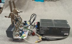
Set up for first listen last night, using a Lambda LRS-53-15 switcher (15V 10A) for power and had a bit of a scare. Powered it up to hum on both channels, louder in the right channel. When the shell of the left input channel contacted the Lambda's chassis - sparks! Long story short: I had installed screw-on feet onto the Lambda so air could circulate. One of the screws was apparently too long and made contact with the 120V mains trace, putting it on the chassis. The momentary 120V on the left input shorted out the 2N2907A on that channel.
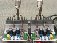
Problems fixed, headphones reconnected, and I was treated to some very nice sounding amps. Gain is just about right, maybe could drop it another dB but G=5 is fine. Dead-quiet in the 'phones. Uber-smooth sound, luscious midrange. Bass not quite as tight and defined as a good class AB with lots of feedback, but not bad at all. Forgot about techincals and listened to music for three hours. That says it all. It sounds very good.
This is with the output transistors taken from the ACDC electronic load - with linear current gain but slow risetime (~1.5V/uS in circuit). Will try the faster MJ15022's and see if that tightens up the low end.
Operating on 15VDC with 500mA static current, with both channels clamped to the HP heatsink shown earlier, heat dissipation was just fine. Not sure if that would be the case if I increase the supply to 18V @ 900mA. We shalll see.
It is possible to leave a current of 500mA.
Yes, but distortion dropped another 2-3dB with 18V 900mA so I want to hear that before deciding.
So if your amp was able to swing its output all the way from rail to rail without any additional distortion, that's 15.0V peak-to-trough: 5.3V RMS. Thus power into 20 ohm load = 1.41 watts. Weren't you seeking 5 to 8 watts when you started?
Yes, but I had also said that 5VRMS was plenty loud, the rest would be for headroom. And that was the case last night - at no time did I notice any distortion, even when playing dense, punchy material. Also, I have a set of Stax electrostats en route and they may require the extra voltage. Their transformers have a lower stepup ratio.
Last edited:
What an honest man. I do things like that and get away with it sometimes. Have you been tempted to try some speakers for fun. You might be pleasantly surprised. Klipshe Forte 2 and a JLH would suit me. Nothing like the Heresy they seem to share parts with. Very refined and a good sound stage. They need a moderate damping factor so don't always suit low feedback tube designs.
Have you been tempted to try some speakers for fun. You might be pleasantly surprised.
Funny you should ask. I was/was not going to build a set of 15 watters for speakers, depending on the outcome of these. I'm encouraged enough so far that I can say, that will happen at some point. As for speakers, I'll use my own. Klipsch is pretty much completely opposite my priorities.
Just for fun, here's the rig used for the listening tests. I've had those fork clamps sitting around for 30 years and never had a use for them until now!
Except for the 100uF, the axial caps are all NOS 50-volt Elnas and Panasonic HF's. Physically large but much lower 120Hz ESR/higher ripple current rating than the junk that came with the kit.
Besides the output transistors, other likely sources of the low-end looseness I'll be looking into: high-ish (50mOhm) output impedance of the Lambda switcher, the relatively small-size (physically) 2200u/35V axial cap on the output (good 2200uF axials are much larger), the amp's high-ish output impedance (compared to an AB). The headphones' transformers are very sensitive to series impedance, even 100mOhms is quite audible.
Attachments
Last edited:
It has already been suggested here to connect a capacitor to a speaker from outside the PCB. More options for replacement.
Pay attention to the capacitance at the input capacitor.
To reduce the output impedance, you can change the feedback circuit.
1. Return to the original (from the manufacturer);
2. Swap the resistor and capacitor from the emitter of the first transistor going to ground (resistor to ground);
3. Connect an additional resistor for feedback from the speaker to the resistor from 2). Additional feedback covers the output capacitor.
Note: This refers to the standard JLH1969 scheme.
I have a pair of the Stax somewhere, Haven't seen them in years. In a shoebox I seem to remember. The headphones I loved were Wharfedale Isodynamics. Whilst not electrostatic they are fussy. I have some Magnapan SMGa of a similar principle. Were it not for the very narrow listening angle they are a near perfect deign. They are loaned out so no idea if a JLH marriage. Having a near resistive 4 ohm load they might be very OK. They nearly have real bass and HF is like real music. Perfect for FM radio. A super tweeter might be something to try.
I like the clamps on the heat-sink.I am building an old Elektor Class AB to drive a Garrard 401 motor. Might use that idea to see how it's going. The Elektor is a version of a 1970s RCA / B&O type idea. A deplorable design which is quite well liked. Sort of like a boat engine of music. It has a bootstrapped input and VAS CCS.
I like the clamps on the heat-sink.I am building an old Elektor Class AB to drive a Garrard 401 motor. Might use that idea to see how it's going. The Elektor is a version of a 1970s RCA / B&O type idea. A deplorable design which is quite well liked. Sort of like a boat engine of music. It has a bootstrapped input and VAS CCS.
Last edited:
To reduce the output impedance, you can change the feedback circuit.
1. Return to the original (from the manufacturer);
2. Swap the resistor and capacitor from the emitter of the first transistor going to ground (resistor to ground);
3. Connect an additional resistor for feedback from the speaker to the resistor from 2). Additional feedback covers the output capacitor.
Note: This refers to the standard JLH1969 scheme.
Hmmm.... doesn't this lower the gain as well? It looks like a resistor in parallel with the existing 2k7 feedback R except at low freq's/DC.
I have a pair of the Stax somewhere, Haven't seen them in years. In a shoebox I seem to remember.
Dig them out and fire them up! I find I prefer headphones while at the computer. The ones I have coming are oldies, SR-X MkIII and SR-5 Gold. But I confess, I'm very tempted to get a new SRS-3100 system, the yen is very weak vs US$ right now and that rig can be had for less than 6 bills delivered from Japan...
But then all this amp work I'm doing would be for nought.
")
The headphones I loved were Wharfedale Isodynamics. Whilst not electrostatic they are fussy. I have some Magnapan SMGa of a similar principle. Were it not for the very narrow listening angle they are a near perfect deign. They are loaned out so no idea if a JLH marriage.
Never heard the Iso's, but I like Maggies, especially in a big room. If you are of an age I think you are, you won't miss that upper 1/2 octave anyway
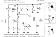
If I recall correctly, they weren't very efficient and needed a pretty beefy amp to drive them to levels where they start to sing.#7834 Simple small amplifier of class AB. # 26
Mid 70's amp distorting pretty badly. High crazy base voltages 20v¿?
Mid 70's amp distorting pretty badly. High crazy base voltages 20v¿?
I find for a 64 year old a super tweeter can open the listening window. I did the maths and found it possible. When I helped Oxford University with hearing tests circa 1990 they thought brain processing speed never changes even when bandwidth does. I hear HF that isn't there when 78s. My mothballed speaker using baffle and Eminence 12lta still needed a sort of super tweeter for 78s. A cheap DT74/8 crossed at 6.6 kHz did the trick. This also saved complex crossovers being used. It opened the listening angle. On signal generator 13 kHz is about my limit.
This is the old war horse I am building. Velleman do it as a very cheap kit. If someone was of a mind to do it it would convert to class A. It is very much like B&O. A friend asked me to design a PSU for her various Garrard turntables. 28 VA load stated 16 W. I really like that the simplest engineering is used. The LTP input using zener and resistor is far better than many imagine. Bootstrap CCS like JLH. Input bootstrap to enable more base current. I dare say some bandwidth limits could be relaxed. One of the famous chip amps died quickly.
A Paul Kemble web page - Elektor 100W Darlington amplifier.
Hi folks,
rather that double post, I thought I would point you to:
https://www.diyaudio.com/forums/sol...gn-files-3.html?posted=1&posted=1#post6582009
- reply No 30 that I have just put up. Its about my testing of an 80 watt Geoff Moss version of the JLH.
The distortion vs power output has an interesting profile.
Regards
Mike
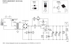
My JLH 1969 (10W) 22V DC
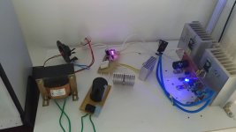
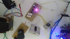
Hello guys, I'm building my JLH 1969 (10W) DC amplifier.
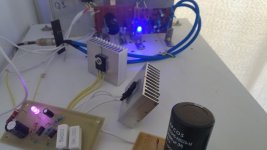
I have now assembled the power supply with a transformer. Linear source with voltage regulator.
IQ = 1.2A
Speaker = 6 ohms.
Circuit = 22V DC
I will organize the components and then make another one of the same for the other side of the audio. (L + R) to stay in stereo.
Hello guys, I'm building my JLH 1969 (10W) DC amplifier.
I have now assembled the power supply with a transformer. Linear source with voltage regulator.
IQ = 1.2A
Speaker = 6 ohms.
Circuit = 22V DC
I will organize the components and then make another one of the same for the other side of the audio. (L + R) to stay in stereo.
Attachments
Hello guys, I'm building my JLH 1969 (10W) DC amplifier.
I have now assembled the power supply with a transformer. Linear source with voltage regulator.
I will organize the components and then make another one of the same for the other side of the audio. (L + R) to stay in stereo.
The amplifier starts with power. Separation of two channels for stereo is best done from two different transformers, but you can limit yourself to one transformer with two secondary windings. After these windings, each channel exists on its own, so we must not forget to multiply everything mentioned by two.
The amplifier starts with power. Separation of two channels for stereo is best done from two different transformers, but you can limit yourself to one transformer with two secondary windings. After these windings, each channel exists on its own, so we must not forget to multiply everything mentioned by two.
Sim, OldDIY esse modelo é para um lado dos áudios (L) por exemplo.
Farei outro circuito de amplificador e de fonte de alimentação para o lado (R).
No total serão 2 transformadores + fontes de alimentação e 2 amplificadores de áudio JLH. Independentes.
 Moderation Edit...
Yes, OldDIY this model is for one side of the audios (L) for example.
I will make another circuit of amplifier and power supply to the side (R).
In total there will be 2 transformers + power supplies and 2 JLH audio amplifiers. Independent.
- Home
- Amplifiers
- Solid State
- JLH 10 Watt class A amplifier