Member
Joined 2009
Paid Member
I used paralleled 2N3055H, these are slow devices and the amp can't push many volts at higher frequencies. It sounds OK though, not as good as I had hoped, perhaps paralleling devices for less beta droop introduced too much base capacitance. But as it s now, it fails to please when compared with a state of art Class AB amp I made.
I used paralleled 2N3055H, these are slow devices and the amp can't push many volts at higher frequencies. It sounds OK though, not as good as I had hoped, perhaps paralleling devices for less beta droop introduced too much base capacitance. But as it s now, it fails to please when compared with a state of art Class AB amp I made.
You got some extra boards for that?
Nigel, the -3dB point can be very high. My comments were for full power (10W RMS), which is based on a distortion analysis rather than observed clipping (which seems to be about 10% before visible on a scope). Third harmonic creeps up faster at higher frequencies near the power limit than at lower powers. If we take the gain reduction as inversely proportional to frequency that would suggest you could still get around 1W at 500kHz. I haven't looked into that specifically, but could go on the list ...
Yes the gain of the output transistors affects THD directly. For most devices the driver current will be around 10mA and a BC337 driver should work. The current gain of the driver will affect THD as well so the higher the better.
I have no idea about your Indian 2N3055's, but I suspect they would have been epi types, as only RCA appears to have built the "real thing" other than perhaps SGS under licence. The frequency response of epi devices is typically 5-6MHz except for the new linear gain/emitter island types which are around 40MHz.
Before fake devices became widely known about I only had one device which failed spec and seemed fake. It was not manufactured by any of the big names but marked by a logo I did not recognise nor did I find out who "claimed" to make it. Often, however, devices built with epi processing won't meet the original second breakdown data sheet limits.
The epi base manufacturing process is the cheapest and these will dominate the production so it pays to buy product from a premium manufacturer.
That has been my experience with 2N3055's.
MJ21194 and MJL21194 may be seen as overkill but they are designed for audio use as matched pairs with MJ21193 and MJL21193.
The datasheet claims low distortion for each partner in complementary pairs and this requires close manufacturing tolerances over a range of both types to achieve this result
The best results for the JLH requires matching the output transistors for gain.
One might have to buy more 3055's to get the same level of matching possible with the 21194's. I would do that and buy the 4 of these I wanted making sure they came from the same production batch.
Hi Bigun
I'm not surprised. I guess your AB amp uses faster OP trannys. If you swap the 2N3055H's for new ones (are ON semi the only guys making them now?) it will sound better.
Some time ago I showed that the problem with 2N3055H was the bootstrap: since it can only rise as fast as the output transistor will drive it, it is not a brilliant solution for audio.
Almost any epi device gives a response to 20kHz and higher.
If you are up to modding your amp, then I suggest reducing the feedback resistor chain, increasing the decoupling, bootstrap and OP capacitors (if it is the original design) too.
I recommend a 33pF across the feedback resistor to prevent oscillations too but this was not essential with 2SC5200's.
If you are driving 4 ohm loads then you may also need to increase the driver current.
mjona- yes, my 100W AB uses MJ21193/4 and has 0.003% THD at 20kHz ...
every time I look at big heatsinks for the Class A I think they'd be better used in an AB amp ...but that is not cool in a thread about Class A!
But I did buy several 2N3055's once and the gains were almost indistiguishable that I could take two and they'd be matched.
I agree matched devices are best, but also if you don't have matched ones use the higher gain in the lower position ... as JLH said.
I certainly recommend matching devices for AB amps. That can even take a 0.003% THD down a little (if not matched originally).
In my recent tests the 3055's were matched as a result, as were the 2SC5200's.
Last edited:
Member
Joined 2009
Paid Member
Hi penmarker, if you are referring to my JLH then no, I didn't make any pcb's. I used veroboard, always wanted to complete a project using that approach and the JLH was the opportunity. Details are here: TGM9 - my version of the JLH '69 Class A amplifierYou got some extra boards for that?
If you are referring to the Class AB amp - no boards available but I posted all the data files you need to order your own from one of the Chinese fabs. A few years back when I made the amplifier it was cheaper to buy your own boards from China that it was to pay me for my time and postage to send them to you! Details here: TGM8 - an amplifier based on Rod Elliot P3a
It says based on P3a, but in reality it was completely redesigned and is now a unique design.
Hi John, It has crossed my mind. The main obstacle is that the power transistors are rivetted to the heatsinks, which I recovered from an old commercial power supply. I'd have to dismantle the amplifier, drill out the rivets and put some new devices in place. I haven't overcome the lazyiness yet but down the road who knows. One idea I had was to add some npn drivers to the output - turn them into Darlington's.Hi Bigun
[...]
If you are up to modding your amp...
If you've had the opportunity to look inside NAD3020 and similar design NAD models, you'd find that most versions required hometaxial power transistors and surprising to me at least, they came from several unusual sources. I believe that RCA was only one of a number of manufacturers, as I also found original semis from Matsushita (National Japan), Toshiba and at least one other I couldn't decipher. Whether these suppliers simply bought dies and assembled them in their own T03 cases, I couldn't say.......I have no idea about your Indian 2N3055's, but I suspect they would have been epi types, as only RCA appears to have built the "real thing" other than perhaps SGS under licence.......
mjona- yes, my 100W AB uses MJ21193/4 and has 0.003% THD at 20kHz ...
every time I look at big heatsinks for the Class A I think they'd be better used in an AB amp ...but that is not cool in a thread about Class A!
But I did buy several 2N3055's once and the gains were almost indistiguishable that I could take two and they'd be matched.
I agree matched devices are best, but also if you don't have matched ones use the higher gain in the lower position ... as JLH said.
I certainly recommend matching devices for AB amps. That can even take a 0.003% THD down a little (if not matched originally).
In my recent tests the 3055's were matched as a result, as were the 2SC5200's.
The way I looked at this was from the perspective of the JLH2005 which uses four output devices increasing the component count the possibility of errors in construction and in achieving a more compact layout than with this version.
You are obviously thinking in terms of a single pair of output devices and both 2SC5200's and MJL21194's are not expensive as they once may have been.
The latter are a little less than twice the price of 2N3055G at RS Components and less than the 2N3055AG in small number quantities.
I think price matters to some people and consider a device with about the same power as two of the cheaper 2N3055G's for the little less outlay.
Would using different NPN's do anything ? Slower on top ? Anyone know about future proof electronic switching in an oscillator. I suspect I will use relays. 4066 isn't ideal as I have 6 Vrms.
Different output transistors can decrease THD (at least in sims). I stumbled across this by chance when i forgot to change the bottom output transistor.
The sims attached ASCs show a draft of a headphone amp for about 1Vrms into low impedance cans.
Total Harmonic Distortion: 0.008358% - Q1 = BD139 Q2 = BD139
Total Harmonic Distortion: 0.001918% - Q1 = BD139 Q2 = D44H11 (top)
Second bias resistor (Rb2) adjusted for approx. equal currents.
Not checked: stability, bleeder resistor, time constants, square wave response ... and maybe the Iqs of Q3 and/or Q4 are too low.
The ASCs are a bit messy - sorry
Attachments
arrangement of components near i/p, heatsinks for the T5/T6, reducing the size a bit and placing a contiguous ground plane on top (blue) results like this.
regards
Prasi
has any one tested this version of JLH circuit? what are the opinions?
The above quoted pcb is as per fig. 2 of The Class-A Amplifier Site - JLH Class-A Update except for bc560 for Q4 to 7 and Q3 as BD139.
regards
Prasi
I made them all, the 69, the 96, the 2000 and the 2005,
personally, I always preferred the 69 which is less lineraire, less flat.
The JLH for esl is very good too but I have less hook, I like the amps
who have a real personality.
I think you'll have answers more technically qualified than mine, me
I rely on listening and whether or not he stays in office.
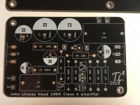
After having JLH '69 without a case for around a year, I decided to finally finish the amp. Wanting to make it better quality than current hand etched pcb and not very tidy psu, I tried tracing pcbs and had them made.
Recently I got my pcbs and I really like how they turned out so I thought I'd share it with you.
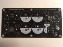
Currently I have one channel of the amp soldered with cheapest parts I could get for testing (it was my first pcb after all), which works perfectly. So now 2 channels with decent parts to come. And also I have soldered one PSU board which works fine except that I had to solder TIP2955 using wires, because someone mixed colector and emiter when redrawing Rod Elliots schematic (damn me ).
).
Recently I got my pcbs and I really like how they turned out so I thought I'd share it with you.
Currently I have one channel of the amp soldered with cheapest parts I could get for testing (it was my first pcb after all), which works perfectly. So now 2 channels with decent parts to come. And also I have soldered one PSU board which works fine except that I had to solder TIP2955 using wires, because someone mixed colector and emiter when redrawing Rod Elliots schematic (damn me
).Attachments
Built with a little care I doubt the JLH 69 has a sound. Real is the most likely one. This it due to very low distortion and what there is as someone said monotonic. There as no hidden switching between power transistors. The sound you can hear is LF and HF filtering. It's hard to prove the latter as the JLH is not bad on that, so not a technical defect. Capacitor types can be heard. Surprisingly the output capacitor is not the worst of the bunch. When you get your JLH working nicely try capacitor size first. Usually adding is the question. That means putting them in paralell with what is already there. I would exspect this to take 3 months of tests. Gain is also worth trying, 120 % and 80 % could be interesting. One type of distortion is class A. If you have speakers and/or ears that don't suit it will sound less real. A pair of Klipsche Forte speakers would cure that.They are the smallest speaker I found to sound real and cost sensible money. Spendor Prelude also, they are nearly domestically sized.
Member
Joined 2009
Paid Member
Cerniu - I like your PCB.
Nigel - my JLH 69 is not exact to the design (very likely because of too many parallel pairs) but it does indeed have a 'sound' in comparison to my low-distortion Class AB amps, and compared with a Class AB amp biassed heavily enough to get Class A for low level listening. I find that the treble in my JLH is a smooth but without much 'air' if I can (yes, I realize some AB amps gain 'air' from their distortion profiles and that would not be a neutral sound) - TBH not sure whare are the right words to use but I found other descriptions of the JLH '69 sound posted on the 'net which uncannily fit my thoughts about this amp. It's a great amp, but to my ears not without a 'sound'.
There were some reports of very good 'sound' resulting from the use of SMPS supply for the JLH 69 around here too.
Last edited:
I understand why you say that and would say the same. The AB can sound better than a class A because most people have become comfortable with the idea of shoe box speakers ( 87 dB/ watt ). If AB distotion can be made to be mostly harmless the AB amplifier is in a general purpose way the better idea. Here is the reason many would not consider. In an AB amplifer the flux levels change inside the power transformer due to current demand and music. If you like the AB type uses the power transformer as a storage devce like the F1 cars. When class A that is not so. Class AB can provide very large peaks with maybe 10% THD. If this is under control that might actually sound better ! That is if the the feedback loop can control it ( notice my local feedback to VAS in my designs, spectrum analysed in voltage and current wave forms required ). The LM324 is an example of when it cant cope. Even pure sine waves upset it, it is not really a defect and can be cured. The designer exspected you to do that or use it into high impedance loads.
To bring the arguement to a correct point. If using a high efficiency speaker like PA systems use you might begin to really hear class A. 100 dB/ watt with 350 watt headroom. When at 1 watt their sound can be very real. I would liken it to a very strong good cup of coffee. What you thought was tonality was clipping. As it's transient it has no obvious sound. The weirder thing is drive units that measure as having no HF actually sound very bright in a nice way. It isn't so much the 100 dB/watt it is the small cone movement that matters. Thus the lineratiy is good. Simply put the coil in the magnet sees very little change in flux.
Returning to the AB advatage. Bob Carver took the energy storage idea a step further. The idea was quite well like. Then Bob did a thing the hi fi world never forgave. He said he could clone the sound of any amp in a hotel room with a suitcase of capacitors and resistors and test gear. Seeing as the Carver amps are viewed in the same way as a diesel engine it was a mad idea. He won. Carver was very honest. He said it showed others have better ears. What Bob did was clone the output using a Null test. He was very brave to do that as it can not compensate for the speaker loading which is reactive. Doubtless he supplied the speakers. Also the Carver Cube reacted badly to fancy cables fashionable at the time. Good old wire was best. Bob showed that what we call amplifier sound is feedback loops and bandwidth limits and being suitable for task. Douglas Self did a class G amp which is a simple version of the same. His is class A/C. I have often thought of simplifying that to use BUZ900/905 as the class A up to 8 watts. If so it would only need a resistor as bias ( 1K pot with 6 mA VAS ). 0.7 amps might start to sound good. That amp could do 150 watts 4 ohms on +/- 55V and use a smaller heatsink than a JLH. It would do 5 watts in A which usually is enough.
Bob Carver - Wikipedia
BTW. It is better to have 100dB/watt speakers as magnetic materials saturate. Saturation is a type of compressor as is the cone moving outside the magnet.
Member
Joined 2009
Paid Member
My listening was done using a large 15" full range driver which is fairly sensitive (the manufacturer claims over 90dB), open back box too.
I remember reading the Carver Challenge. A very sobering read for anybody who has spent a small fortune on a branded amplifier believing it will sound better.
I remember reading the Carver Challenge. A very sobering read for anybody who has spent a small fortune on a branded amplifier believing it will sound better.
- Home
- Amplifiers
- Solid State
- JLH 10 Watt class A amplifier