For fun I did a JLH Naim NAP140 Hybrid drawing. What stopped me showing it was the 8.2K 180K long tail pair resistors. Maybe it would be fine, The idea greatly simplifies the build and allows high resistance feedback loop if wanted ( 2 K inverting input ). The current setting same as 1969 with bootstrap current source. The JLH is the better bootstrap I've seen.
To keep the simplicity I would use a split tail resistor with capacitor. As the long tail pair in this use is a current amplifier the tail being short is not a big problem. Make the tail 80% perhaps. One can take it to a high voltage with it's own PSU, That has virtue. As we are almost switching off TR2 we need not bother.
Input resistance is whatever you want. 10 K seems OK.
https://assets.nexperia.com/documents/data-sheet/BCV62.pdf
Ready made current mirror. Dual PNP and NPN exist as two devices . Mostly better than hand matching. If NAP 140 no need to match.
Ready made current mirror. Dual PNP and NPN exist as two devices . Mostly better than hand matching. If NAP 140 no need to match.
Last edited:
Good morning guys!
I want to thank Mjona and Fredbloggstwo for the directions provided to me.
Unfortunately for the moment I have to postpone the experimentations, the wife wants to go on vacation and I have to settle. When I come back I propose to resume the thing and continue. For now, thanks and greetings.
Mleod
My hate of airports soon clears my head. An A4 pad and pencil are my Internet. If I have that I seldom switch it on. It's just there if I need it. My phone never had it activated. I think I get into holiday mood quicker than Colleen.
mjona,
Intuition based on experience and knowledge is better than numbers with no connection to reality. Nowadays scientists and laymen rely extensively on algorithmic randomness as a short and convenient way to knowledge, but they fool themselves profoundly. It is a deplorable mistake to believe that the propositions of mathematics are statements of reality. Propositions do not hold any empirical information and do not have any factual implications. Mathematical models do not help explain the unknown and do not help ignorance. Mathematics does not contribute anything to empirical knowledge. No information is better than false information.
Loading is not taken into account so calculations are worthless. I avoid high gain transistors if I can, especially in transconductance stages, but I do not make calculations.
I do not read papers where orthodox terminology is used anymore, but thanks anyway.
What is your take on the JLH amplifier?
People who work with number seldom have no connection with reality. In fact I would say it's impossible. No, it's the most impossible thing I can imagine.
Calculations like DC voltage relating to RMS output is useful. The JLH is not bad on that.
Why would you avoid high gain transistors in a transconductance stage?
Mathamatics are the only thing that explains the unknown. What might be hard to explain is a subjective feeling.
Empirical is a valid fast track in engineering. Sometimes we can spend months saying the solutions of others are the best. Or we try new things and if very lucky find a better way. Often my best ideas were errors that worked.
There is plenty of room for using maths to question things. Chemistry and conduction is not as neat as you might think. Aluminium and Sodium as examples. Recently for my peace of mind I invented " conductivity per unit mass". It's so obvious I won't say well done to myself. What it did do is say that per unit mass Aluminium is remarkable which doesn't fit the explanations of free electrons often given. I then calculated that Mercury being common is a mystery and suspected the even number of electrons favour it over Gold. The maths of a 10 year old took me on that journey. The ultimate example being semiconductors. BTW, electrons being near the atom centre I doubt is as important as is implied. Again Aluminium says that. This was something I did for my boss.
BTW. Nearly all aircraft solutions are empirical. Mostly we are holding the structure away from turbulance. We can drive through that point and if sustained it can be safe. That's not how it's done for domestic aircraft. There is no computer in the world that can aid that situation and if the maths is correct none ever will. It's Chaos theory maths. The good news is a wing designed and built to a good design will always be the same and can be reproduced. If a larger wing is made it's a new design. The old one is training for the engineers, mostly it's a new concept. The little wing ends common now are a great idea. They make the maths work by stopping the upper and lower wind currents mixing in an unhelpful way. Some still argue over wing design and say it's more the angle to the air. Biplanes did not have the obvious assistance of the underwing yet they fly. You have to put the fuel and tyres somewhere. Given some thought the Biplane conforms to the same way of working.
Heat sinks. I often find by maths I make them too small. I think it's that things clamped togther or in a tight space get hotter than thought. I am often wrong by 30 %. Now I just add that on.
Heat sinks. I often find by maths I make them too small. I think it's that things clamped togther or in a tight space get hotter than thought. I am often wrong by 30 %. Now I just add that on.
Last edited:
Loading is not taken into account so calculations are worthless. I avoid high gain transistors if I can, especially in transconductance stages, but I do not make calculations.
For what its worth, I did an experiement on Geoff Moss' JLH version of changing the driver 2SC3421 (with a Hfe of 160) with a very high Hfe BD437 (with a Hfe of 860). The measured distortion stayed the same, but the sound went very muddy - and I am one to vere more to the objective than subjective side.
I also seem to remember an article by Stan Curtis (?) in the Linear Audio magazine where he was brought 'simulations of great power amp designs' by up and coming audio designers, that had (simulated) noise and distortion dropping through the floor, but when prototypes were built and put to the test and measured and sounded awful.
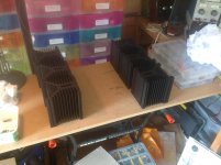
For some interest, here are some pictures of my monobloc Moss/JLH in the making. - "Call that a heatsink?" (Nigel?)
This is a re-housing of this amp since my first attempt had bright heatsinks and got a wee hot at 46C. or so, and I wanted to add more output transistors.
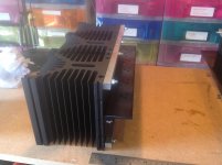
The black horizontal bar going front to back is the heat spreader linking the 3 heatsinks to the 3 pairs (up to 5) O/P transistors. I needed this amount due to my Matrix 801 S3s dipping down to just above 5 Ohms or so. One bank of heatsinks take the upper O/P transistor set (with one of the cap multiplier power devices) and the other the lower set.
The heatsink anodising was all stripped back and redone to aircraft standard by a local firm when they did the spreader plate.
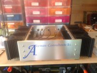
I decided to put the transformers for both amps along with the soft start, rectifier and initial smoothing in a separate case. The amp case then contains further smoothing and the cap multiplier.
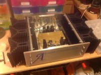
The unpopulated PCB going across the amp left to right is where the O/P tranistors come together. The O/P transistor cables all terminate with crimp n' solder connections onto stainless steel/high tensile nuts and bolts. The PCB tracks also have some 'magic sauce' added.
")
It measures about 0.008 to 0.01 or so on distortion measurements, but importantly, sounds smooth and power without effort to my ears.
Kind regards,
Mike
Attachments
mjona,
Intuition based on experience and knowledge is better than numbers with no connection to reality. Nowadays scientists and laymen rely extensively on algorithmic randomness as a short and convenient way to knowledge, but they fool themselves profoundly. It is a deplorable mistake to believe that the propositions of mathematics are statements of reality. Propositions do not hold any empirical information and do not have any factual implications. Mathematical models do not help explain the unknown and do not help ignorance. Mathematics does not contribute anything to empirical knowledge. No information is better than false information.
Loading is not taken into account so calculations are worthless. I avoid high gain transistors if I can, especially in transconductance stages, but I do not make calculations.
I do not read papers where orthodox terminology is used anymore, but thanks anyway.
What is your take on the JLH amplifier?
I built both versions and am still using the 1996 version that I built nearly 22 years ago. This was 20 years after I had built the 1969 version of the circuit.
Between these dates there had been Class B projects from magazines and a couple of examples where I cobbled together a circuit using my preferences for a final version built in 1990.
I have been doing simulations for a few years now - firstly because of my interest in repairs and then to help out where circuits failed to work.
A simulation of the 1990 circuit simulation confirmed that it should work but with a couple capacitor value changes it should work better but it can stay unused on the shelf.
My view on simulations is the accuracy of the predictions depends on the accuracy of the .models used.
There are variations in Beta and Vbe between examples of parts of the same number and heating silicon increases the mobility of electrons that need some thought in regard to interpretation.
I think it useful also to study wave forms and Tian plots to decide whether or not a circuit might be viable.
All these tests are within a range of tools that can be used but only for guidance but the decision should be made from a wider perspective including the element of intuition.
I think a circuit can have a higher THD and sound correct if the order of the harmonics is monotonic.
In other words it has to emulate the JLH Class A characteristics - but with less heat output which is still a dream.
I think a circuit can have a higher THD and sound correct if the order of the harmonics is monotonic.
In other words it has to emulate the JLH Class A characteristics - but with less heat output which is still a dream.
+1
For what its worth, I did an experiement on Geoff Moss' JLH version of changing the driver 2SC3421 (with a Hfe of 160) with a very high Hfe BD437 (with a Hfe of 860). The measured distortion stayed the same, but the sound went very muddy - and I am one to vere more to the objective than subjective side.
The SC3421 has better frequency characteristic - having an fT of 120 MHz the point where the gain declines to unity (equal to 1). The BD437 has higher gain but the point where the gain declines to unity is 3 MHz.
The stability of the JLH relies on the fT of the 2N3055's in the output having the lowest in the component line up.
The figure is 2MHz while the BD437 fT is greater at 3MHz this only applies where the gain is unity or 1.
Another way of describing the 3MHz is as gain bandwidth product so a closed loop gain of 13 rather than 1 has implications in a nfb divider network as you have seen.
I avoid high gain transistors if I can, especially in transconductance stages, but I do not make calculations.
I did an experiement on Geoff Moss' JLH version of changing the driver 2SC3421 (with a Hfe of 160) with a very high Hfe BD437 (with a Hfe of 860). The measured distortion stayed the same, but the sound went very muddy
BD437 is a bad transistor, period. If you want to experiment with the effect of Hfe, use the same transistor type, different only in Hfe (for example comparing grade C with grade F), then you can draw a better conclusion.
For me, in VAS, the most important variable is Cob. The tendency is, the higher the Hfe the higher the Cob (of different transistor type), so that you may not seeing Hfe in action but Cob.
Cob is very important as it affects proper compensation in feedback amplifier. Hfe is also important. There are many known simple circuits (3 gain stages: input-VAS-output) where we choose by hand the highest possible Hfe for the VAS (of the same transistor type) to get the best sound.
For output stages, it depends on the circuit topology whether we should aim for the lowest Cob (hence low current transconductance) or for the highest current.
Last edited:
The SC3421 is superior Japanese technique, but not a video transistor.
N101N, what parameter that you specifically need from a video transistor?
Those have small Cob and are made for high voltage-low current operation as current and bandwidth are inversely related. For example, 2SC3600, 2SC3417. To avoid saturation, I would use them, say, at 5 mA reaching an exceedingly impressive 350 MHz static frequency limit. The 2SC3953 can manage heavier load.
The nominal value of reverse transfer capacitance for the 2SK135 is 10 pF. (A good candidate for the JLH amplifier).
The nominal value of reverse transfer capacitance for the 2SK135 is 10 pF. (A good candidate for the JLH amplifier).
For me, in VAS, the most important variable is Cob. The tendency is, the higher the Hfe the higher the Cob (of different transistor type), so that you may not seeing Hfe in action but Cob.
For output stages, it depends on the circuit topology whether we should aim for the lowest Cob (hence low current transconductance) or for the highest current.
In a way you are thinking of Miller effect in a common emitter stage. In these there is also some small loss of gain due to Early Effect. For more on these subjects you can check out sources on web.
Those have small Cob and are made for high voltage-low current operation as current and bandwidth are inversely related. For example, 2SC3600, 2SC3417. To avoid saturation, I would use them, say, at 5 mA reaching an exceedingly impressive 350 MHz static frequency limit. The 2SC3953 can manage heavier load.
The nominal value of reverse transfer capacitance for the 2SK135 is 10 pF. (A good candidate for the JLH amplifier).
Tell us in plain words one can understand why a 2SC3600 is suitable for the phase-split transistor in the JLH Class A circuit.
Those have small Cob and are made for high voltage-low current operation as current and bandwidth are inversely related.
Yes, that's right, but non video transistor can have similar properties.
When I look at video transistors I observe the linearity first, then the current because they can be too small, then whether they have complementary part. 2SA1381 is a popular video transistor with a matching part (2SC3503) that is linear. But if you purchase Fairchild pairs with the same grade, your chance to get a closely matched pair is small.
2SA1360 is OTOH considered as 'audio transistor' instead of 'video transistor' (though the properties are similar). It is capable of less current, 50mA versus 100mA (so it may be a positive thing for you). IIRC, 2SA1360 is more linear and better matched with its complementary part.
In a way you are thinking of Miller effect in a common emitter stage. In these there is also some small loss of gain due to Early Effect. For more on these subjects you can check out sources on web.
Yes. But for VAS duties, the options are limited, so that we would already know the properties of our transistor candidates, including the VAF. That's why I can say some numbers without consulting the pdf when I talked about my favorite transistors
I think a repetitive mistake often said here ( more so if here ) is Ft. The JLH will work well with the 2N3055. As John said the JLH overcomes the weaknesses of the devices in the interchange of the two NPN outputs. Douglas Self thought it a poor idea as he finds it hard to analyse ( I guess ). Most modern devices as Self points out are able to maintain high gain at high current. I suspect if the " better " devices sound better it is the easy drive. Like your JLH had power steering. If you think about it this makes sense as the JLH lacks a driver in the usual way. When a valve amp these are usually gain of +/- 1 ( 2 differential ). The Quad 11 being an exception.
- Home
- Amplifiers
- Solid State
- JLH 10 Watt class A amplifier