Electronically regulated power supply
Talking about regulated supply... with LM386 chip amps, Dan Joffe says:
GT-102 Stereo Power Amplifier
[PDF] https://www.akitika.com/documents/AssemblyManualGT102rev1p14.pdf
page 44: Power Supply Schematic
page 45: Amplifier Module Schematic
Talking about regulated supply... with LM386 chip amps, Dan Joffe says:
GT-102 Stereo Power Amplifier
Class AB with a Regulated Supply...Approaching Class A?
The GT-102 has an electronically regulated power supply. That makes it unusual among audio power amplifers. But in some ways, it offers an advantage similar to class A operation.
Class A amplifiers can be among the most linear of amplifiers, and the least efficient. They draw a constant current from the power supply, no matter what signal is being delivered to the speaker. That says that a Class A amplifier doesn't modulate the supply rails..constant current drain produces a constant load on the power supply, and hence a constant voltage.
Is a Class AB amplifier with an electronically regulated power supply almost as good in that respect? If the power supply's output impedance is low, then the output signal minimally modulates the rails. That should cause less distortion at the output. In that sense, the Class AB with regulated power supply should be about as blameless as a Class A amp.
The one way that the Class A amplifier still has it over the Class AB is that at low listening levels, the output device has nearly constant current. That is, its operating current is the large class A bias current with the small signal modulations. Of course, at high output levels, the Class A advantage diminishes, as the output device then experiences wide swings in operating current.
[PDF] https://www.akitika.com/documents/AssemblyManualGT102rev1p14.pdf
page 44: Power Supply Schematic
page 45: Amplifier Module Schematic
Last edited:
These Chinese distributors infuriate me - why can't they employ just ONE person who speaks/writes colloquial English, instead of producing this meaningless tripe? If you're going to issue something at all in "English", why not make a tiny effort to make sure it's vaguely intelligible?
I have run into this a number of times. My guess is they plug the copy into a translator and this is the crap that comes out
I hope this will be usefulhas anyone built this amp?
Attachments
Sounds very good. No doubt. Thanks. And, of course, much much better than every big and bigger, costly and more costly solid state amp or pre-power-combi;-)
Want build a (quasi-) JLH with sot-32 transes now;-) I will report. I do expect better contour and more snappy and better "space-time"-)
Want build a (quasi-) JLH with sot-32 transes now;-) I will report. I do expect better contour and more snappy and better "space-time"-)
Haha, they probably do it just to annoy youThese Chinese distributors infuriate me - why can't they employ just ONE person who speaks/writes colloquial English, instead of producing this meaningless tripe? If you're going to issue something at all in "English", why not make a tiny effort to make sure it's vaguely intelligible?
") . They have a totally different cultural outlook, blatantly ripping off western designs is also not a problem, if you want, studying their history it's very interesting and can help to answer the why
. They have a totally different cultural outlook, blatantly ripping off western designs is also not a problem, if you want, studying their history it's very interesting and can help to answer the whyJohn Linsley Hood
JLH made this amplifier to equal the 1969 design whilst giving more power. The original was a triple using MJ3001 and its compliment. Very interesting compenstaion observations. Alas I only found the usual one to work when my BC337-40+33pF. You might count this as a triple like idea as FET's work like Darlingtons in terms of current gain, there is plenty of drive as in this mode CgS is important ( not so much a source follower where the load bootstraps the CgS ). On the face of it this is a no-no idea. JLH finds it very stable!!!! It's a drain output like a complimentary feedback pair's collector output. Nothing is faster than a MOS FET so I tend to discount that the triple is automatically trouble. Exicon 10N/P20 is circa 500 pF.
I set the current as JLH showed. It worked first time. 100R 560R seems ideal and Vbe won't be vastly different for many devices. For me it is up and running in 20 seconds and is as solid as a rock. My heatsink might be 0.25C/W, that might be a big deal. I suspect BC337 will be too small if the outputs are low gain and current set high. The examples JLH ( 3/8/15R 17/27/36 V 2A/1.2A/0.9A ) gave seem to look OK. If you find things fluctuating you almost certainly have oscillation in the early MHz. Being class A you should have a chance to cure it. Watch the tweeters if taking a chance.
I see no harm in using a fast device with a capacitor. It makes a super-slow device as both gain and cap quality are better.
Here is another hero design with the triple.
http://www.diyaudio.com/forums/solid-state/134733-crimson-krimson-amp-schematics.html#post1683167
And
http://www.bryston.com/PDF/Schematics/3B-8BST_SCHEMATICS.pdf
yes !I hope this will be useful
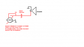
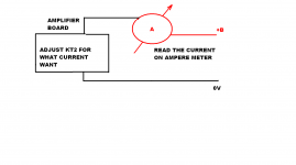
in first,adjust the mid point of the supply
in 2nd,ajust the quiescent current with ampermeter to 1.2A (with no signal input)
re-ajust the mid point of the supply
and re control the quiescent current after one hour
Don't know about Bryston, but the reason I bought many Crimson amplifiers is because they did sound good.The Crimson and the Bryston do not sound good. Tooo complex, too many (much;-) stages and complementary-parts. No chance. I would neither build, nor unpack, to listen;-)-;
The Crimson and the Bryston do not sound good. Tooo complex, too many (much;-) stages and complementary-parts. No chance. I would neither build, nor unpack, to listen;-)-;
I hate mine (3B and 4B) for more than ten years.
I never listen to them every day, too complicated, too heavy
experience has taught me that you should never have a negative view on an amp before listening to it and it is because of that (or because of that) that I have thirty or so amp today
i love crimson 630c but I've never managed to buy twoDon't know about Bryston, but the reason I bought many Crimson amplifiers is because they did sound good.
you know C-audio amp ?Don't know about Bryston, but the reason I bought many Crimson amplifiers is because they did sound good.
i have both model ,great and good amp
Are you sure that's not just how you feel it should be? The Crimson does need checking for stablity. It can sound very good.
The complexity of the Bryston seems to suggest they had trouble. The JLH FET double looks very interesting.
The thing to understand is both class AB and D set very big engineering problems with very great rewards if sucess comes ( that's the question ). Class A like here completely avoids the problems. Switching speeds and dead bands do not come into it, nor even latch up. My one doubt is can the input transistor supply current under all conditions. By using an ultra high gain second transistor that doubt in made minimal. The fact I need to limit frequency responce is shown to be real at 160 kHz which seems plenty. Remember this is not class AB and there is no switching.
I just had an interesting thought. Douglas Self does see linearity advantages in certain fast devices, read carefully as he never says fast is better although supports that idea passively by not really stating it. He then uses a Cdom of 100pF and 7mA load. My guess 47pF typical at a current of 20mA is the typical JLH ( 13.5V/ ( 100+560R ) typical ). That looks a good point of debate. Don't be fooled by the 0.7V/2200 = 320uA emitter resistor, anyone thought why it's that value? My guess is he set it by trial and error. It would allow all the current to enter the base, the 2K2 setting the turn on point.
One person on another thread said " a two stage amplifier can't go unstable as the total phase shift can never be > 180 degrees" he was talking about a mythical JLH. That can be annoyingly true with oscillators. Often if the gain factor is high enough they are happy to oscillate. The JLH is arguably a 2.X stage amplifer in that the the current source is modulated by the collector of the second transistor ( not greatly I think, the PSU says not at all ). Two pieces of advice on this. If you have no oscilloscope try various Cdom by ear ( for want of a name, mine BC337-40 33pF NPO/COG ceramic ). Mine shows marginal instability on square-waves. Some say that's the optimum point, there is no residual in the spectrum when sine wave tested at power. Square-waves show very mild over shoot. As the amplifer has no output choke the square-wave test is really saying something. You might fit a 4R7+100nF Zobel network in paralell with the speaker. Use a 0.6 watt resistor. If it gets warm you have some oscillation. Seeing as a JLH will work without one I would say not having a Zobel is a bigger thing than 2SC5200's over 2N3055. It seems my Indian 3055 are very good on gain. I have real doubts they can be bettered. What many don't see is the speed of the device is of no real importances in this amplifier. Gain is and might be a by-product. By the way. Today after some burn in the amp or oscillator is giving 10kHz 7 watts second harmonic -62 dB third - 69 dB. As I know for a fact that's very close to what the oscillator can give it is just possible the real figures are better. It can go either way. Seeing as this is a well known design I am starting to think I have broken my personal sound barrier. That is 0.1% THD with Jean Hiraga style exponential harmonics of distortion. If you think of the input stage it could be. The ear hears that as zero distortion as the differenece harmonic to harmonic is as the ear hears. That suggests an amplifier with only 0.001% all fifth and seventh will sound worse. That's the thing the 1950's tests didn't guess as no amplifiers of the time could do that. It's perfectly possible to make an amplifer like that. A bit of hiss would help it!
Here is something I did for another thread. It was to show that something very simple and very cheap could replace a LM7812 or LM317 and when required a LD1084. All are devices I like for their reliable results. If you like something JLH might have thought up. Basically the V-LED- Vbe x 1K/100R gives you your output voltage ( the Sziklai pair has gain ). I found 330uF about the best choice for the primary ripple filter at the LED. It is also a hiss filter. The V drop out voltage is wonderfully low and is trying to work at 0.55V ( out just lower ripple than in, fully working at 0.7V ). I guess any big PNP usuable, mine was cheapest device I had plenty of and too small for this. I would think a fast one fine. I had no problems. This remarkable feedback pair might just work as it is at unity gain as the JLH prime transistor. If so linarity could be excelllent along with drive being easier. If you want mildly less hiss from the regulator use more LED's and less gain. 3 LED's seems ideal if 12V. The 56R was my load. Call it 20R if this amp. If so make the pre regulator voltage as small as possible. Main cap must have a ripple rating of >6 amps I would say if using more current than me for 4 ohms load. The LED was thought to be an ideal Band Gap if wondering. TL431 needs measuring gear if tempted. I could imagine 7 LED's for 27V would be about right. They glow very dimly used this way. I imagine it could clean up a switch mode. If you measure 28.5 V in and 27 V out it stands a chance of working. As the ripple is more switch mode than this device a smaller and lower ripple current capacitor could be used. If you see the PSU current limiter flicker well after start up a small resistor between the two could help. 0R22 comes to mind.
C-audio. Yes. In some ways like 1980 JLH. I like HH-1200 as it shows just how cheaply the Hitachi 1979 amplifer could be made. MPSA42/92 to replace 2SB716 2SD756 and 2SA872A. HH gives 600 watts RMS and very low distortion with a design slightly less complex than the JLH. And it is safe. The BBC used them as a general amp for years. I can borrow a C-Audio anytime I like. The HH shows how many things you read are not true. If you believe what you read the HH would struggle to do 20 kHz. The truth is a Audio MOSFET needs about 2 mA to get to full power 20 kHz. The 1nF total CgS is bootstrapped so isn't the problem is seems. Thus the MPSA 42's drives many pairs. As the MPSA 42/92 can do 270V safely the HH can exploit that. Exicon sell match VgS sets of FET's to get the most from HH and simialr amps. HH let the FET's self regulate which more or less works. I would imagine a matched set could be worth 20% more power.
cool !! thank's !!C-audio. Yes. In some ways like 1980 JLH. I like HH-1200 as it shows just how cheaply the Hitachi 1979 amplifer could be made. MPSA42/92 to replace 2SB716 2SD756 and 2SA872A. HH gives 600 watts RMS and very low distortion with a design slightly less complex than the JLH. And it is safe. The BBC used them as a general amp for years. I can borrow a C-Audio anytime I like. The HH shows how many things you read are not true. If you believe what you read the HH would struggle to do 20 kHz. The truth is a Audio MOSFET needs about 2 mA to get to full power 20 kHz. The 1nF total CgS is bootstrapped so isn't the problem is seems. Thus the MPSA 42's drives many pairs. As the MPSA 42/92 can do 270V safely the HH can exploit that. Exicon sell match VgS sets of FET's to get the most from HH and simialr amps. HH let the FET's self regulate which more or less works. I would imagine a matched set could be worth 20% more power.
i have two HH v800 unstable .
purchased for spare (j50/k135) and I did not resolve to disassemble them
Would the PA duty be the FET PCBs, or the CE3004?Yes Andrew. The guy with the C-Audio's has a special PA version of the Crimson. John Deans thinks he may have been Crimsons first big customer.
Would the PA duty be the FET PCBs, or the CE3004?
I will try to find out. John like myself is dyslexic. Shame as I think you would really like him. He just does not do email ( he has an address where silence is usual ). I think his versions were first ever made.
Here are my 1 watt results. Notice the drop off of the graph of where the 2N3055's cut off is very gradual. I put a 2 MHz marker in, it was oscllatng at 500 kHz before fitting 33pF to BC337-40, still a mild hint of it I choose to keep. You can just see the 7.5 V peak to the left of the 10 kHz. It looks to be 0.02% THD 10 kHz. I have no real idea as the oscillator is not really good enough. Looks it could be true.
Off to buy some food now.

Last edited:

With SMPS. Notice the very low 1 watt 10 kHz distortion is equaled. However above 40 kHz we see the SMPS noise. Arguably being > 60 kHz we might not know it's there. I have a 0R33 + 1000 uF as a simple filter. It is a Mean Well RS-50-24 which gives 28.1V max. My bigger doubt is sending noise into CD players or whatever via the 230V. I won't use it. I have a hunch it will be better than it looks.
my experience with LAMBDA JWS600 24v/27a is not convincing.
With SMPS. Notice the very low 1 watt 10 kHz distortion is equaled. However above 40 kHz we see the SMPS noise. Arguably being > 60 kHz we might not know it's there. I have a 0R33 + 1000 uF as a simple filter. It is a Mean Well RS-50-24 which gives 28.1V max. My bigger doubt is sending noise into CD players or whatever via the 230V. I won't use it. I have a hunch it will be better than it looks.
i had lost heat ,same to with classe D amp .
now I use it only for testing
- Home
- Amplifiers
- Solid State
- JLH 10 Watt class A amplifier