
Buy from here.2SC3264-O - Power Transistor 230V 17A
They are original.
They are original.
mouser radiospare and farnell too ,and yet I bought fake at each of them.is a big pro seller's
the only one I'm pretty sure about is Donberg.ie but their price is often prohibitive.
I prefer to buy amp breakdowns knowing what's inside to recover original quality parts
although, I have a doubt ...mouser radiospare and farnell too ,and yet I bought fake at each of them.
the only one I'm pretty sure about is Donberg.ie but their price is often prohibitive.
I prefer to buy amp breakdowns knowing what's inside to recover original quality parts
Semiconductor: 2SA1295 (2SA 1295) - TRANSISTOR SILICON PNP / 230V / 17A / 130W / 35MHz...
I would buy from Profusion I ordered several times the high power and other lateral (EXICON) mosfets and I am very pleased with them. I did order from Donmberg electronics a few years ago and they sold me authentic parts! I don't think these companies deal with shadowy people with fake parts. I can recommend both of them without a doubt.
Are you sure emitter of Q4 2N5551 should be connected to base of Q3 2N5401?
Well spotted
")
Q4 is upside down and I never noticed. The simulation actually runs in that condition which is remarkable.
I have many amplifiers using them.for this price,i can assure you it's a fake
All hard tested many times in the past
I would buy from Profusion I ordered several times the high power and other lateral (EXICON) mosfets and I am very pleased with them. I did order from Donmberg electronics a few years ago and they sold me authentic parts! I don't think these companies deal with shadowy people with fake parts. I can recommend both of them without a doubt.
ok, I want to believe you.I have many amplifiers using them.
All hard tested many times in the past
so bought fake, I'm probably paranoid
Update on BC327/337/2N3055. No 4100. It is remarkably stable both AC and DC wise. The PSU I'm using is reasonably good so gives noise at -102 dBV ( It should be far better as LM723 is used which could give -112dB ref below 1Vrms ) and hum at -83 dBV at 1.2 amps. Hiss is only -90 dBV as I have no preamp to shunt it yet. The input impedance circa 55K. Most interesting is the switch on surge is only 1.7A ( 1.2A after 1 minute ) and seems mostly related to DC points as hot or cold it's the same. I speculate the PNP and NPN devices are doing more than we think.
You may wonder why I use very low grade 2N3055 and BC327/337-40. Reading JLH it seems to be he is saying it will best that way. If so these devices are available and highly unlikely to be fakes. It is very hard to fake a ultra high gain device. I strongly doubt my 2N3055 are really 2N3055. I suspect they are any OK device in a TO3 case. They seem to have very nice gain. I would think they are > 1MHz. Indications are more like a 2N3055H.
To get perfect balance needs 100K upper and 120K lower DC setting resistors ( perfectly with the maths ). This will vary with device and grade. My BC327/337 show> 400 on cheap hfe tester.
My shed had show last night and was at only 5C. The house at 17C and rising. DC mid point virtually identical shed or house. For a class A amp that's rather good. I wonder if JLH went into enough detail over the maths, I think he did many calculations to get to the ideal design. It looks to me this design is far more sophisticated than it seems. I wonder if the Folk Law of the current setting being very dependant on all things being right is in fact the truth in action. If the heat sink is too small it will be trouble. For me it has been rock solid. My heat sink at a guess is 0.25C/W. I have two so might not change anything. If you do the maths what do you gain to double the watts? 10 times is where it starts to matter. Even then it's the PSU one is forced to have that helps.
I have some doubts I am too lazy to check. Some say the open loop gain is 60 dB. That implies circa 35 dB to control distortion. Seeing how hard the BC337( 2N697 ) works it seems unlikely. Open loop without the 2N3055's perhaps.
I now have a big problem. I can't find my test gear. I do have a digital device which is terrible although great for power tests. What I might do is build a multipole filter at 1 kHz and 10 kHz. Sometimes these are not as good as they should be. I need 0.0003% THD to know. A NE5532 might be OK. One way I can do it is the 1820 method ( Fourier ). That is to look at in and out and say what has changed. Even so it needs to be lower distortion than what I have to hand. I do have a RA53 thermistor which sweet spots with 680R. If I build a sine cosine two stage Wien Bridge I should be somewhere near my target, I hope to have a bit of common mode distortion nullling . Output at 1V rms should be fine. 2 x PP3 batteries to help hum levels. BTW. A small lamp can be made to work in a Wien. Even ones with very low initial resistance. Christmas tree lamps can work. It needs to be the opposite way to the long obsolete RA53 in feedback arm as it has the opposite resistance current responce.
My chinese P type JLH is sounding good and better than I expected. So good that Im going
to resist trying to improve it but build another one with all the best ideas from forums like this.
Ive got some 2SC2922 gain group P (70-140 hfe) which are similar to the 2SC3294.
I know they are real as Ive had them over 15 years so that should be a start. These
are high ft so should I be worried about the possibility of oscillation ? Simulation would help but I
dont have the device models. Anyone have any suitable links for them ?
I agree about the sophistication of this apparently simple amp. This is what's got me interested in it again.
When its finished it will be an interesting comparison with my rebuilt 300B amp (when thats finished !)
Some say the open loop gain is 60 dB. That implies circa 35 dB to control distortion. Seeing how hard the BC337( 2N697 ) works it seems unlikely. Open loop without the 2N3055's perhaps.
Well......
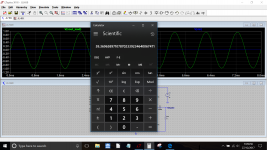
As a very rough and ready check I get this as the OLG at 1khz.
Attachments
I posted this thinking it was here, but realised it was in the Siliconray trade thread which is probably dead.
I built one of these amps using the Siliconray boards some years ago which hasn't been used. I recently ran it for a few days and had problems with the L channel blowing the pcb fuse. Having checked it over it seems that I can't now get the dc offset down and my light bulb tester is glowing brightly when the L channel only is connected (dual mono double psu design)
I Built the board using TIP3055 transistors. My electronics knowledge has increased a little since I built that amp and I have a few questions I wonder if anyone can answer.
I used the TIP 3055's in both positions on the board, but now wonder whether they should both be the same or whether one of them should have been a P channel 2955. I am probably going to replace all the output transistors on both boards and wondered which ones would be favourite for the board's interpretation of the JLH amp.
60dB ! Thanks.
Just hit my first snag with the JLH. I get significant 2MHz oscillation if using 100R to substitute a preamp at the input ( 100R, rest as JLH ). How everything is grounded is prime. I think I will use my not very good oscillator ( schools/lab type ) and do some basic testing. My feeeling is this will be a basic question of the design and not the Ft of devices. If using Chinese clone kits did they sort it out? The inverting input might be better. I would hate to loose the purity of the design if unable to nail down the origine. None the less it's going well. The BC337 hasn't given up yet.
Just hit my first snag with the JLH. I get significant 2MHz oscillation if using 100R to substitute a preamp at the input ( 100R, rest as JLH ). How everything is grounded is prime. I think I will use my not very good oscillator ( schools/lab type ) and do some basic testing. My feeeling is this will be a basic question of the design and not the Ft of devices. If using Chinese clone kits did they sort it out? The inverting input might be better. I would hate to loose the purity of the design if unable to nail down the origine. None the less it's going well. The BC337 hasn't given up yet.
no.I posted this thinking it was here, but realised it was in the Siliconray trade thread which is probably dead.
I built one of these amps using the Siliconray boards some years ago which hasn't been used. I recently ran it for a few days and had problems with the L channel blowing the pcb fuse. Having checked it over it seems that I can't now get the dc offset down and my light bulb tester is glowing brightly when the L channel only is connected (dual mono double psu design)
I Built the board using TIP3055 transistors. My electronics knowledge has increased a little since I built that amp and I have a few questions I wonder if anyone can answer.
I used the TIP 3055's in both positions on the board, but now wonder whether they should both be the same or whether one of them should have been a P channel 2955. I am probably going to replace all the output transistors on both boards and wondered which ones would be favourite for the board's interpretation of the JLH amp.
all output transistor are N
this amp is hard to adjust and stabilize.
first, check BD 139/140 and avoid high gain.
I took mine a long time ago because it worked less than my 69 or 96 but he never blown a fuse

Does run. Very well,-) Not as hard and brutal and clear as the 3 parts 5 W SE, but more smooth, and more snappy than the TO-3P SE.
The most would cry...-)
...something to do; amp of a friend, to "update"-)))
C-:
YouTube
The most would cry...-)
...something to do; amp of a friend, to "update"-)))
C-:
YouTube
Attachments
![IMG_20171227_202949[1].jpg](/community/data/attachments/605/605467-a25c145c7967d29fcd21cd501c16e6d6.jpg)
- Home
- Amplifiers
- Solid State
- JLH 10 Watt class A amplifier