Calculate the current through each and then multiply by the voltage across each.
Isnt it an obvious answer?, that you so kindly post every time you get an opportunity?
I can do a sim in LT when I have time, but you should be in a position to make a guess that I am busy doing layouts. Making layout is a hard, time consuming activity. there are so many builders of this amp that some one could reply immediately. There is no need to reinvent the wheel repeatedly every time you are building or making a layout for amplifier thats being tested all over the world since 1969/2003!!!
Come on! be a sport , try to help really!, like others did in previous few posts by making suggestions
Hi Prasi,
AndrewT makes one understand the reasoning. That is not a bad thing because you will know how to go about it in future. Just giving the answer is sometimes too easy and nobody cares about how it is found.
Besides that, unless everyone is going to uses the same transformers, the same power transistors and adjust for the same bias current then the answer is quite simple, but this rarely is the case.
So let us say that the current that you selected was one Amp and the resistance 100 m Ohm then it would need to dissipate 100 mW (I^2 x R).
This however is not totally straight forward because you have to de-rate the resistor power for temperature and you really need the resistor curves to find the factor.
If you use your rule of thumb, I guess going 50% higher would be safe and as gaborbela suggested elsewhere 1 watt should be plenty while remaining physically small.
I recommend that these resistors be mounted off board by a few mm, so when they get hot, and they do, your board will not turn brown underneath them with time.
Hi Prasi
Very nice work. I really enjoy the JLH sound, how many Watt are we talking about here, assuming a typical +/- 25vdc supply a la Pass F5 ?
I have a bunch of 15003 waiting to be put to good use
BR,
Eric
Hi
Please see the attach. at post #3745...
I hope that help
")
To Prasi I love the layout, thank you! Lets see how much interest we get may be a small GB.. who knows. Also lets wait on other people advise suggestion so on.
Thanks guys for your suggestions,
If 220uf is mandatory, I can put additional pads. Vishay RN60D can be fitted easily in the current version.
regards
Prasi
220uF is not mandatory, many people use 100 uF sometimes as small as 47uF, it is all to do with how far you are from the power supply and these caps prevent what is referred to as "motor boating" which is caused by the sudden inrush of current and the voltage drop on the wire from the power supply which in turn snubs the current and the process starts again. A loud BRRRR sound.
Your choice of 220uF is good for most cases unless a builder is going to put his power supply in a different box some 500 mm or more away, I would say in that case cap could be 470 -1000uF. Do not worry about this because it will come out in the wash after some built it and find some "discrepancies" and one knows where to solve the problem. Going too big in this cap is an unnecessary expense because there is no too big value.
In my opinion you cannot cater for every DIY whim, in a universal design, the DIYer has to make some decisions regarding stability issues of his choices as as well.
Prasi, I think you are doing a great job and the layout is pretty nice.
Last edited:
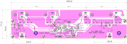
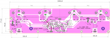
Prasi, I have one problem with the layout and the DIYers will have to make a decision.
One does not jump the supply through a transistor case, simply because the screw may not be tightened and so forth. I would not change your layout but I would recommend that the power supply is jumped between the power transistor screws with insulated wire soldered under the board.
One does not jump the supply through a transistor case, simply because the screw may not be tightened and so forth. I would not change your layout but I would recommend that the power supply is jumped between the power transistor screws with insulated wire soldered under the board.
Prasi, I have one problem with the layout and the DIYers will have to make a decision.
One does not jump the supply through a transistor case, simply because the screw may not be tightened and so forth. I would not change your layout but I would recommend that the power supply is jumped between the power transistor screws with insulated wire soldered under the board.
Nico I see what you say. and yes if the some of those screws become lose it can cause some problem. Not necessary but still the possibilities there.
Hi Prasi,
AndrewT makes one understand the reasoning. That is not a bad thing because you will know how to go about it in future. Just giving the answer is sometimes too easy and nobody cares about how it is found.
Besides that, unless everyone is going to uses the same transformers, the same power transistors and adjust for the same bias current then the answer is quite simple, but this rarely is the case.
So let us say that the current that you selected was one Amp and the resistance 100 m Ohm then it would need to dissipate 100 mW (I^2 x R).
This however is not totally straight forward because you have to de-rate the resistor power for temperature and you really need the resistor curves to find the factor.
If you use your rule of thumb, I guess going 50% higher would be safe and as gaborbela suggested elsewhere 1 watt should be plenty while remaining physically small.
I recommend that these resistors be mounted off board by a few mm, so when they get hot, and they do, your board will not turn brown underneath them with time.
Hi Nico,
That's what I was looking for when I asked my question, now that's what is really helpful(your current post), like your previous post too, which gave me ideas. Unlike some generic didactic reply.
thanks for your help.
I know Andrew's intentions, but due to lack of time, one is not able to follow through entirely and sometimes the tone fiddles the wrong nerve
. Prasi
Sorry for being pedantic. There is a potential earth loop if a stereo amp is running on a common earth, I would move C4 closer to R11, cut the bridge between the main ground and the 0V island you created and couple these two grounds with a small value resistor, 10 ohms or so. I think my reasoning is obvious that there could be a ground loop created between the screen wires in the input connection between amp and source.
Of course the DIYer can lift the input ground at the input terminals as well, then there is no need for this change in the PCboard. This is not something on JLH schematic, its just an experience.
Of course the DIYer can lift the input ground at the input terminals as well, then there is no need for this change in the PCboard. This is not something on JLH schematic, its just an experience.
Last edited:
Prasi, I have one problem with the layout and the DIYers will have to make a decision.
One does not jump the supply through a transistor case, simply because the screw may not be tightened and so forth. I would not change your layout but I would recommend that the power supply is jumped between the power transistor screws with insulated wire soldered under the board.
Ok Nico,
I will post an instruction on the layout itself to jumper the supply with insulated wire from Q2 C to C1, Q2A C to C1 and Q1A C to C1, Q1 C to C1.
thats a nice mechanical consideration of design, i missed out.
Nico & Prasi
Do you think something like these would be a solution with out a big modification?
Just an idea..
Should not be a problem, but Prasi is the designer.....
Prasi, I take back my comment on the ground loop, the only way is to do it on the input connector as the huge ground plane on your board has little more purpose than that of connecting the two caps to ground.
It would be pointless decoupling that little island. Don't change anything, you just need to remind the fellows that should they have a hum loop they do one of the following: Decouple the connector grounds through 10 Ohm to the main board ground, or..... Disconnect the screened input cable at one point so that the two screens do not follow a loop.
It would be pointless decoupling that little island. Don't change anything, you just need to remind the fellows that should they have a hum loop they do one of the following: Decouple the connector grounds through 10 Ohm to the main board ground, or..... Disconnect the screened input cable at one point so that the two screens do not follow a loop.
The two inputs screens are each the other half of the input signal circuit. One must not break either screen connection.Prasi, I take back my comment on the ground loop, the only way is to do it on the input connector as the huge ground plane on your board has little more purpose than that of connecting the two caps to ground.
It would be pointless decoupling that little island. Don't change anything, you just need to remind the fellows that should they have a hum loop they do one of the following: Decouple the connector grounds through 10 Ohm to the main board ground, or..... Disconnect the screened input cable at one point so that the two screens do not follow a loop.
You should implement HBRR/HBRL as described by D.Joffe for a stereo/multi-channel amplifier.
- Home
- Amplifiers
- Solid State
- JLH 10 Watt class A amplifier