If I understand you correctly you are thinking about using a 6.3V cap in the feedback cct. This raises some interesting points.
In both of the JLH versions of this cct he has this cap going to the neg most rail of the amp. this means that there is a voltage of much more than 6.3V across it.
I have noticed that some people have the newer dual rail version of the amp with this C4 connected to earth rather than the neg rail. This would certainly mean that a 6.3V cap should be OK. But the are two reasons why this may not be the best way to go ( if indeed you intend to keep this cap in the cct atall ).
I believe that JLH kept the cap going to the neg rail because he was of the opinion that electrolytics caps work better with a polarising voltage across them which would not be the case if it is run to earth. Also generally speaking the higher the voltage of an electrolytic the better it sounds so using this logic it would be best to go for a higher voltage 470uF going to the neg rail.
Perhaps there are some people that have tried both ways and could shed some light on this.
personally I would try to go for the no C4 option and put up with a highish DC offset. no cap sounds as good as no cap !
My only question would be does DC offset affect the operation of any ferrus cored chokes in the crossover. I'm not sure on this point but I am sure that if these are replaced with air core ones the sound improves considerably !
cheers
mike
p.s. I'm not familiar with this esl version, is there a diagram somewhere to look at ? If the amp is driving a transformer, DC offset could be bad news.
Been thinking about C4 a bit on my 96 recently. Mainly because I've been concerned about it being reverse polarised when the signal goes below 0V (not scared it will go pop, just not ideal behaviour).
Mike mentions above his theory that JLH used a negative rail instead of 0V, in order to keep the cap polarised correctly at all times. Geoff has pointed out on his website this can induce extraneous hum and should be avoided.
So, what would happen, if instead of grounded, the cap was attached to a seperate, well decoupled, perhaps regulated, negative power rail. It's not a huge signal being filtered, with a lot of current. Do you think this could work?
Obviously, the other option is to bypass the cap completely with a link - and this whole discussion is irrelevant.
Phil, try two elkos back to back to GND. Bias the
midpoint to Negative through high value resistor.
Not too high resistor, it might take unacceptably
long time for DC offset to settle its normal value...
Yeah, but then I'd need a cap on the output.
At the moment, it's just a hypothetical discussion. I was just wondering if it could be a possible compromise between using ground and reverse polarising a cap, and using the negative rail and injecting hum into the feedback loop.
Sorry, my misunderstanding.
by back to back, you mean in series, midpoint being between them.
i thought you were suggesting one reverse polarity in parallel, and then adding a dc offset somewhere to the signal so that the capacitors were polarised accordingly (not sure how that'd work really).
I was tired!
I guess you'd need a reasonably high resistor or you'd affect the filter characteristics (although possibly in a way we'd like it to behave I suppose).
Free PCB for JLH 2005
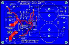
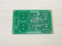
OK, I sent the PCB file to our own PCB factory this morning. Fab out will be on next monday. I'm assuming 0.01/pc for this board equals free offer. Anybody has interests in it can get one here:
Free JLH Class-A amplifier board
Each order is limited to 2pcs
OK, I sent the PCB file to our own PCB factory this morning. Fab out will be on next monday. I'm assuming 0.01/pc for this board equals free offer. Anybody has interests in it can get one here:
Free JLH Class-A amplifier board
Each order is limited to 2pcs
OK, I sent the PCB file to our own PCB factory this morning. Fab out will be on next monday. I'm assuming 0.01/pc for this board equals free offer. Anybody has interests in it can get one here:
Free JLH Class-A amplifier board
Each order is limited to 2pcs
Hi siliconray,
How can I get this pcb in free? thanks..
Regards,
Boyet
Hi boyet, just order from the link in the information you quoted. the price is $0.01, I'm assmuing it's equal to free because can't set tozero price. What you need to pay is only shipping cost.
Here's the link again:
Free JLH Class-A amplifier board
Here's the link again:
Free JLH Class-A amplifier board
Testing Result
Got one soldered today. Overall the result is positive. Found some problems:
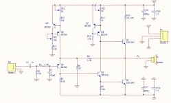
1. The VR1 should be 200Ohm (it was 2k on the schematic I posted before)
2. R13 should be 22Ohm (was 200Ohm on the schematic I posted beofre)
3. Pad hole of for BD140 is too small
Others are OK. I use BD139 as subsititute of 2SC3421 because it's hard to find. Supplied with +-18V, quisent current about 2A, 8Ohm load, the sound is quite good.
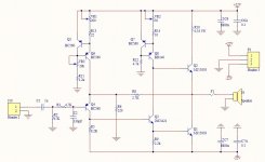
updated schematic is attached
problems on PCB will be fixed.
Keep on supplying free boards.
Got one soldered today. Overall the result is positive. Found some problems:
1. The VR1 should be 200Ohm (it was 2k on the schematic I posted before)
2. R13 should be 22Ohm (was 200Ohm on the schematic I posted beofre)
3. Pad hole of for BD140 is too small
Others are OK. I use BD139 as subsititute of 2SC3421 because it's hard to find. Supplied with +-18V, quisent current about 2A, 8Ohm load, the sound is quite good.
updated schematic is attached
problems on PCB will be fixed.
Keep on supplying free boards.
Attachments
Last edited:
I am a bit concerned for the SOAR of Q8 BD140...
On the downswing, current and voltage here are
simultaneously quite high.
Not so much to blow this device instantly, and
maybe fine for half wave duty, but your peak is
well outside the lines for continuous DC...
Figure as much as 250mA if traditional 2n3055
were abused as output devices. And -48V peak
voltage at this collector. Then look the BD140
spec sheet... Maybe the lower base current of
MJE15003 saves your bacon? I'm just sayin...
With 4 ohm speakers and less capable outputs,
the bias required could take Q8 completely off
SOAR and into oblivion!
Q3 is under much less stress, even though the
current and voltage peaks are same. They are
happening in opposite phase... Here I wouldn't
hesitate to use BD140's compliment, BD139...
Last edited:
I am a bit concerned for the SOAR of Q8 BD140...
On the downswing, current and voltage here are
simultaneously quite high.
Not so much to blow this device instantly, and
maybe fine for half wave duty, but your peak is
well outside the lines for continuous DC...
Figure as much as 250mA if traditional 2n3055
were abused as output devices. And -48V peak
voltage at this collector. Then look the BD140
spec sheet... Maybe the lower base current of
MJE15003 saves your bacon? I'm just sayin...
With 4 ohm speakers and less capable outputs,
the bias required could take Q8 completely off
SOAR and into oblivion!
Q3 is under much less stress, even though the
current and voltage peaks are same. They are
happening in opposite phase... Here I wouldn't
hesitate to use BD140's compliment, BD139...
Maybe TIP32C in TO220 for Q8?
If you gotta fix the pad size anyways....
- Home
- Amplifiers
- Solid State
- JLH 10 Watt class A amplifier