Hi,
Are there any patents on the JLH amplifier topology, other than this one Low output impedance feedback power amplifier ?
Thank you.
I read it , Almost the same topology with JLH except Feedback Link and TR's PNP , NPN reverse . 10 Years before JLH. Amazing.
Can anyone who have built or know the JLH high power dual supply and dual output transistor (2005) design well, tell me about the 2k7 feedback (gain) resistor. I would like to increase the gain by using a 4k7. This change simulates well but I would like to know (1)will it have an effect on the distortion and (2) would it be working in class AB and not in class A anymore?
Thank you in advance
Thank you in advance
Without looking at the circuit , a quick guess is that distortion will rise with greater gain but that doesn't mean it will sound any worse as it will still be low ! The class A condition is determined by the output stage bias. If you don't change this the amp will still be in class A mode.
Choke Inputs and Critical inductance
A choke shouldn't be that expensive (if price mattered that much we'd be using $2 class-d things and wall warts") ) particularly as the standing current is quite large, so one does not need much inductance (stick critical inductance into your favorite search engine).
) particularly as the standing current is quite large, so one does not need much inductance (stick critical inductance into your favorite search engine).
Back of the napkin scribble suggests that simply using another power transformer (secondary) as the choke might work. Real world would require some inductance measurement!
It's certainly less trouble than a fully regulated power supply.
And it's lighter than the only truly quiet power supply - batteries.
Ironically I believe that I once owned a home made guitar amp which was a JLH or similar with a choke input power supply - at the time I couldn't understand why all the output devices were the same type; it had three large hunks iron; made almost no watts and ran really hot. To this day I wish I'd reverse engineered it.
Yes but the price difference between the choke and a resistor is big. Also I have a resisto pi filter that helps a lot, but I want something more, thats I a am asking these questions.
A choke shouldn't be that expensive (if price mattered that much we'd be using $2 class-d things and wall warts
) particularly as the standing current is quite large, so one does not need much inductance (stick critical inductance into your favorite search engine).Back of the napkin scribble suggests that simply using another power transformer (secondary) as the choke might work. Real world would require some inductance measurement!
It's certainly less trouble than a fully regulated power supply.
And it's lighter than the only truly quiet power supply - batteries.
Ironically I believe that I once owned a home made guitar amp which was a JLH or similar with a choke input power supply - at the time I couldn't understand why all the output devices were the same type; it had three large hunks iron; made almost no watts and ran really hot. To this day I wish I'd reverse engineered it.
Just a brief update. Have built two modules, JLH 96 with MJ15003s. Module has its own input and output sockets (I'm using Speakons so it's harder to short the output), just requires power and 12V from a regulator for setting DC offset (might mount that in the module too). Needs a lot of tidying up (I need to use solder and heatshrink instead of chocblock for some of the joins ), but pretty good for a work in progress so far.
Going to get them cooking and ensure they have similar DC offset and Iq, then I'll have a listen in stereo for the first time !
), but pretty good for a work in progress so far. Going to get them cooking and ensure they have similar DC offset and Iq, then I'll have a listen in stereo for the first time !
Attachments
Well, heard them last night in unison. Listening rather quietly (they're still in the garage - where I could annoy the neighbours), so Iq was about 1A. The PSU is unchanged, so 20,000uF per rail shared between the two channels. There is currently very little hum, not drastically more than when running a single channel. the 7812 regulator is feeding both dc offset settings. I had started knocking up a capacitance multiplier, but I'm not sure I'll bother now - maybe add some more capacitance.
I was impressed when I heard it as a single channel, but in stereo, blimey!
Even when the speakers are just 0.5 m apart, the imaging is pretty awesome. Singers and instruments are surprisingly well detached, and central from the speakers.
And this using a bogstandard CD player.
Now to build a chassis for it and the psu.
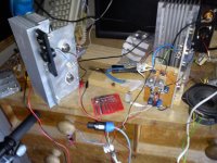
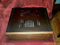
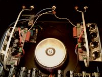
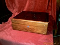
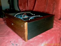
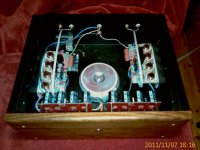
I just completed a high power derivative of the 1996 dual supply JLH design. By completed I mean in a box and I screwed the lid on last night. I actually completed it a while ago and was tweaking / playing with components and variants up to know. My wife said that as long as the lid is open I will never finish it. So last night I finished it
I will post some pics here soon. I think it is a very special amplifier and by using a few "exotic" components it has become a superb amplifier. If someone is interested I could list a few of these components.
It is delivering around 50W rms into an 8 ohm load as I have it running on 35V rails and a quiescent current of 2A.
I have compared it to other bought and modified amps with A/B listening tests and it outshines them easily.
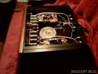
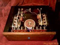
Here are some pics taken with my cellphone so the quality is not great.
Components I used that I call exotic aren't really exotic but are not components you will get from the local "Radio Shack" but are freely available on the net. Each component I will list here made an audible improvent, some more than others but changed the amp from good to great.
Starting from input of one amplifier:
Jupiter 6N 26 gauge hookup wire
Russian paper in oil K72 0.47uF capacitor - high-pass filter at input
Silver Mica capacitor - low pass filter at input
Tantalum type resistors in signal path - input filter, feedback and gain resistors
All other resistors Audio grade carbons
Toshiba transistors except output which is MJ15003
CCS capacitor - 100uF Nichicon FP low ESR
Feedback cap 470uF Elna Silmic II
Attachments
Last edited:
Very nice
Does changing hookup wire really make a notable difference?
I'm already on the lookout for some paper in oil caps...
Yes, I was also skeptical especially such a short piece of wire.... but it does. It made a big difference. Almost as much as the input capacitor did. The previous wire I used was a piece of no-name brand shielded audio cable that I cut from a RCA cable that was lying around. To be honest compared, the old wire sounded constipated
compared.ok, so by hook up wire, you mean from the phono input to the input on the board. Sorry, I thought you meant in general. I think that's pretty good practice to at least shield that part of the signal path. I simply used some cheap old interconnect you get free with a CD player or something and cut it up to suit - better than the single cat5 core I had before.
Output transistors
Hi to everyone,
Newbie here so I hope I'm not derailing the present topic. I've just completed a four channnel amp using slightly modified 1996 circuits which was built from four kits from APJ audio and they're supplied with 2N3055 transistors. I know this has been a topic previously, but to save me wading through all the posts, how significant is the sound difference with MJ15003's or as I seen elsewhere 2N3773 transistors? I thought I'd get opinions before I spend even more money. I believe the MJ is favourite for sound quality but I've also been aware of fake transistors going around. Any other member heard about this?
I've also been looking at the discussions between members on PSU configurations, just to let you know I'm using +/-12V supplies via 50A/hr deep cycle leisure batteries. The sound is fabulous, no hum, no noise and no interference from crap on the mains supply. I know this resricts maximum output power but I'm using fostex horns front and back so sound levels are not a problem.
Cheers
I've simmed this circuit upside down and sideways, and can
draw some simulated conclusions. Take with simulated salt...
Synergy with imperfect driver transistor (possibly Early effect)
appears to cancel out some beta droop distortion in 2n3055's.
Replacement of 2n3055 with a less droopy modern type never
goes into the base current range where both the problem and
the magic of this cancellation occurs.
This circuit can definitely help old 2n3055 to give its best!
That is not saying 2n3055 is best transistor for this circuit.
So far, of all SPICE models from sources that I can trust,
2SC5200 seems to have the upper hand. But you might
do have to reduce the drive bias. Better transistors will
demand less total drive current for the same output bias.
Distortion can be reduced tenfold by avoiding beta droop.
Last edited:
Hi to everyone,
...how significant is the sound difference with MJ15003's or as I seen elsewhere 2N3773 transistors? I thought I'd get opinions before I spend even more money.
Cheers
I can't comment on the 2N3773 as I haven't tried it but the improvement from changing from the 2N3055 to the MJ15003 is substantial. The bass becomes firmer and the treble/midrange becomes cleaner and more focussed. It is one of the best upgrades I ever made to my JLH.
Tim
- Home
- Amplifiers
- Solid State
- JLH 10 Watt class A amplifier