CCS TNNUTS?..
Here you can see the current reference circuit and here from that thread is an interesting post where the originator may have omitted the 1K resistor shown in this image.
Beyond overcoming these interesting saturation effects there are other interesting active and passive compensatory methods to further improve performance; the thermal and transient behaviours of these circuit types are also worthy of study.
My question here is; 'Is there anyone here (or somewhere else) that knows of any prior existence if this CCS?', let me know!
Here you can see the current reference circuit and here from that thread is an interesting post where the originator may have omitted the 1K resistor shown in this image.
Beyond overcoming these interesting saturation effects there are other interesting active and passive compensatory methods to further improve performance; the thermal and transient behaviours of these circuit types are also worthy of study.
Diego[/QUOTE]
Cool
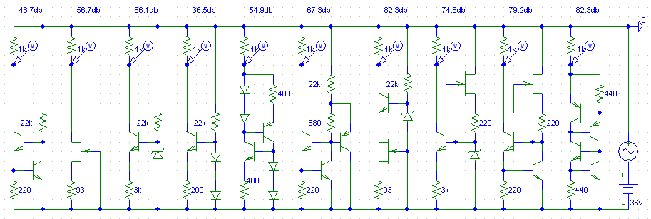
I'm not alone. It's a shame that I can not claim the invention but I can live with that.From all the circuits in the 1st and 3rd link I would claim that the 4-transistor floating CCS is the 'best', for the added cost of one component (replacing the zener with 2 transistors is even cheaper (when compared to the other 82dB CCS))), it gives the same performance as the second placed one (and it works always provided that you use 2 pairs of exact the same transistors IMHO). Dynamically it is behaving very good and the PSSR is 'extreme' this circuit deserves more attention as you noted.
It is very interesting that the 4-transistor version can perform as good as simulated (and tested) because there is no 'dirty' bias connection.
Finding out that starts it stable by using the 'extra' 2 internal resistors was a good 'invention' found by Ricardo.
My first time usage of this circuit is more then 30 years old.
Jfet cascoded Jfet is superior to all, but has voltage and current limitations.
for higher voltages a supertex depletion mosfet is a good choice.
The voltage limitation in Jfet's did lead to the selection of this circuit.
I will apreciate your comments... will do the same after every step on my upgrade list.
That's a lot of data, I need a bit of time to digest it
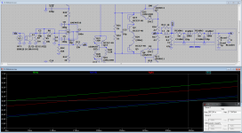
Ok..... Not that complex, there is pahse shift between DC to 20Hz and also phase shift from 20kHt up (the shift shifts between these two measurements)
Anyway, I just replaced the 10k resistor by your latest CCS and also reduced the miller cap from 100p to 15p (that is what I had around)..... Now I get an overall reduction in gain ( from 20dB to 19dB) but stable over 200kHz...... Interesting.
Now I will experiment with the new bias circuit..... pics latter.
Ok..... Not that complex, there is pahse shift between DC to 20Hz and also phase shift from 20kHt up (the shift shifts between these two measurements)
Anyway, I just replaced the 10k resistor by your latest CCS and also reduced the miller cap from 100p to 15p (that is what I had around)..... Now I get an overall reduction in gain ( from 20dB to 19dB) but stable over 200kHz...... Interesting.
Now I will experiment with the new bias circuit..... pics latter.
The miller-cap should be (in my last schema) 10p (NOT 100
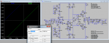
) (so you where using 100?) The picture shows the 'phase-shift' using the faulty 100p capacitor! Almost 2uSSee also #351 http://www.diyaudio.com/forums/anal...rainer-nobrainer-discrete-36.html#post3835270
P.s. Your scope shows about 2uS of shift.
Attachments
Last edited:
The miller-cap should be (in my last schema) 10p (NOT 100
See also #351 http://www.diyaudio.com/forums/anal...rainer-nobrainer-discrete-36.html#post3835270
P.s. Your scope shows about 2uS of shift.
I told you, These measurements where made in my stock build that uses 100p miller as per jg suggestion " Due to the lower Ft of the D44/45 parts you may need to enlarge C6 the miller cap. Experiment with 100p to 1n"
I told you, These measurements where made in my stock build that uses 100p miller as per jg suggestion " Due to the lower Ft of the D44/45 parts you may need to enlarge C6 the miller cap. Experiment with 100p to 1n"
O.k. cool, but I wanted to make this clear for everyone following this
no harm intended.Now measurements are much better looking. bandwith is now near 5hz to 150khz.
Time to work on the new bias circuit.
Just have one question. In my stock build I measure bias around 13mA, but using the simulator I can get only as low as 50mA.... How can I be sure what the resulting current will be with a 7mA ccs ?
Time to work on the new bias circuit.
Just have one question. In my stock build I measure bias around 13mA, but using the simulator I can get only as low as 50mA.... How can I be sure what the resulting current will be with a 7mA ccs ?
Just have one question. In my stock build I measure bias around 13mA, but using the simulator I can get only as low as 50mA.... How can I be sure what the resulting current will be with a 7mA ccs ?
You can not, device tolerances will make sure of that. But it will be near enough. The bias current of the amplifier must be trimmed, due to these device variances.
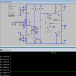
Look at the sim:63mA bias
How can I get 13mA from the simulator ?
You must drop at the least one bias trans-diodes, 4 is to much, make it a trio
then trim with the resistor. As noted before: the 4 trans-diode bias is overcompensated and for that reason alone you should drop one of the trans-diodes.Hi,
with my basic Sim parameters it takes quite long to calculate operating points and waveforms.
Also waverforms of certain nodes show very narrow spikes.
After my experience this hints to problems like onset of oscillation and similar.
I used a OPA134 model instead of a generic OPAmp and different output transistors as I have no model of the D44.
CFP-outputs typically require some compensation.
To prevent oscillation I included CB-caps across the driver transistors (typically something between 100pF and 220pF suffices).
That stopped sim issues immidiately.
Still though as soon as the CFP aproaches from class-A to class-AB the current waveforms of the negative branch look unusual compressed.
jauu
Calvin
Hi,
with my basic Sim parameters it takes quite long to calculate operating points and waveforms.
Also waverforms of certain nodes show very narrow spikes.
After my experience this hints to problems like onset of oscillation and similar.
I used a OPA134 model instead of a generic OPAmp and different output transistors as I have no model of the D44.
CFP-outputs typically require some compensation.
To prevent oscillation I included CB-caps across the driver transistors (typically something between 100pF and 220pF suffices).
That stopped sim issues immidiately.
Still though as soon as the CFP aproaches from class-A to class-AB the current waveforms of the negative branch look unusual compressed.
jauu
Calvin
The models that I used are poster here in the thread. Large spikes in the simulator output are not an indication of possible oscillations (IMHO) but more likely a result of infinity's in the calculations it could also be that the model of the OPA134 is faulty. To see stability of the circuit you need to look at OLG (open loop gain) (there are a few samples included with LTspice (but I'm not sure if you are using LTspice)).
- Status
- This old topic is closed. If you want to reopen this topic, contact a moderator using the "Report Post" button.
- Home
- Source & Line
- Analogue Source
- JG´s Nobrainer and Nobrainer Discrete