I am using the 49710 opamp... but with 100p miller cap.... this is a good sign.....
Now, why do you use three transdiodes and not only two and increase the bias resistor a little bit ?
And here is something special indeed: Krylov - Bach - Toccata and Fugue - YouTube
This guy (Sergej Krilov) might as well be the highest violin player alive")
Where is the 'Like' button
(on this site)Sure, just curious.
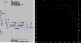
Here they are, 3 graphs
1st at GFB
2nd at output
3rd at loudspeaker
Attachments
I am really positive about the outcome..... the "stock" build sounds really good for it's simplicity.... now I believe I will have a really SOTA little amp
I started this build just to know the principles of power amps in a hands on approach...
Just bought a new scope and a function generator.... I am taking this seriously.
Also learning a lot in the process
I started this build just to know the principles of power amps in a hands on approach...
Just bought a new scope and a function generator.... I am taking this seriously.
Also learning a lot in the process
I am really positive about the outcome..... the "stock" build sounds really good for it's simplicity.... now I believe I will have a really SOTA little amp
I started this build just to know the principles of power amps in a hands on approach...
Just bought a new scope and a function generator.... I am taking this seriously.
Also learning a lot in the process
I repost the graph, some scales where missing.Attachments
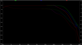
Been measuring my build and found the bandwidth to be 7Hz to 95kHz at -3dB
Gain is a lowish 9.6x 20dB
No ringing with square waves so I can surely reduce the miller cap.
Just received a nice "cadeau" from a friend so I will now start to build FdW version with a CCS for the mirror and a new bias circuit.
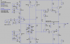
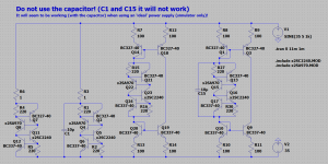
One thing I do not understand in the latest schematic......
The signal coming from the opamp does not hit the transdiodes in the middle. The signal is fed into the resistor part of the bias circuit. Why not using all three transdiodes of the same polarity NPN then ?
Also, in the latest schematic I see a 100n miller cap but I read before that a much smaller one can be used..... how low can I go ?
Gain is a lowish 9.6x 20dB
No ringing with square waves so I can surely reduce the miller cap.
Just received a nice "cadeau" from a friend so I will now start to build FdW version with a CCS for the mirror and a new bias circuit.
One thing I do not understand in the latest schematic......
The signal coming from the opamp does not hit the transdiodes in the middle. The signal is fed into the resistor part of the bias circuit. Why not using all three transdiodes of the same polarity NPN then ?
Also, in the latest schematic I see a 100n miller cap but I read before that a much smaller one can be used..... how low can I go ?
Been measuring my build and found the bandwidth to be 7Hz to 95kHz at -3dB
Gain is a lowish 9.6x 20dB
No ringing with square waves so I can surely reduce the miller cap.
Just received a nice "cadeau" from a friend so I will now start to build FdW version with a CCS for the mirror and a new bias circuit.
One thing I do not understand in the latest schematic......
The signal coming from the opamp does not hit the transdiodes in the middle. The signal is fed into the resistor part of the bias circuit. Why not using all three transdiodes of the same polarity NPN then ?
Also, in the latest schematic I see a 100n miller cap but I read before that a much smaller one can be used..... how low can I go ?
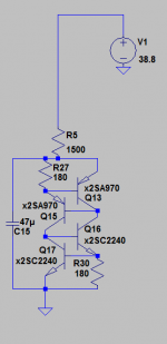
The trans diodes are a bit to much
by dividing the bias current over the trans diodes and the parallel resistors the thermal regulation is improved and the opamp feeds at precisely the halfway point between the output stage transistors, that improves output symmetry and offset regulation.It is better to limit bandwidth to a 'sensible' range, this will give you a more stable amplifier, less prone to external signals fouling its response and more control over capacitive loads... .
Wrong answer (the previous one (now edited out)) (sorry), I had to see where that 100n is, went to the diagram and found that the 'miller' is 10p(C1), the 100n(C7) is part of the opamp PSU HF decoupling.
Last edited:
Been measuring my build and found the bandwidth to be 7Hz to 95kHz at -3dB
Actualy, if you want to know the amplifier GBW, you should measure at the global-feedback-point (marked gfb).
When you measure GBW at the output then you include the zobel, the cable and the output inductor. These are all changeable, you could make the zobel impedance higher (e.g. R19 to 15 Ohm and C2 to 22n), you could remove the inductor (I do not advice to go lower then 1u
) and you may improve the cable specifications (here 5m Ohm and 100nH parallel to 330p per meter).Although it is valid to do this (measure GBW at the output) and this is where it is mostly done, it is not the place where you, as a designer, take your measurements when optimizing the amplifier circuit.
Ok, I was wrong, the 100n cap is not the miller cap..... should be more carefull reading your circuit.
But I did not understand your answer.... why not use only NPN bjt for Q2 Q5 and Q14 ?
I am measuring the build with a scope and I do not use a zobel or coil in the output. The load is a simple 8ohm woofer.
But I did not understand your answer.... why not use only NPN bjt for Q2 Q5 and Q14 ?
I am measuring the build with a scope and I do not use a zobel or coil in the output. The load is a simple 8ohm woofer.
Attachments
Good to see that the 'cadeau' arrived
Yes.... now I am willing to surprise you in return
But I did not understand your answer.... why not use only NPN bjt for Q2 Q5 and Q14 ?
Why not? They where there (when you did draw the sim
) and I left them (but I did remove one, it was way over compensated).As I did say before, I need to do some more work on the thermal compensation.
Currently, the 3 transistors and the parallel resistors, give a reasonable stable bias but it can (and should) be improved.
At the moment I'm a bit ill and not doing much other then complain to the wife, as soon as I'm a bit fitter it will be done. For now it can be build as is.
- Status
- This old topic is closed. If you want to reopen this topic, contact a moderator using the "Report Post" button.
- Home
- Source & Line
- Analogue Source
- JG´s Nobrainer and Nobrainer Discrete