Hi Calvin.... welcome aboard ")
Please explain what you mean by compensating the CFP..... I do not detect any oscillations so far.
my simulations also show compression in the negative side but only when operating into class A. Do not know what it means.
I would really like to let this build work in class A for the 1st what and then merge into class AB.
I am nor sure what should be the ideal bias current .... please advise.
Also, I do not know if this build is prone to thermal runaway if I push it too far, so a limit would be welcome.
You must drop at the least one bias trans-diodes, 4 is to much, make it a trio
Will do it today.
Please advise on the best possible approach for bias current in order to get class A operation on the first 1 watt output
Hi Calvin.... welcome aboard
Please explain what you mean by compensating the CFP..... I do not detect any oscillations so far.
my simulations also show compression in the negative side but only when operating into class A. Do not know what it means.
I would really like to let this build work in class A for the 1st what and then merge into class AB.
I am nor sure what should be the ideal bias current .... please advise.
Also, I do not know if this build is prone to thermal runaway if I push it too far, so a limit would be welcome.
The CFP does not need compensation due to the large amount of degeneration that is being used in this amplifier. (is my current opinion
)Start with a bias of 1.1 * I where I is Sqrt(P / R) [You can figure it out
P = 1
R = 8
I = 353mA
1.1 x I = 389mA
Am I right ?
P = 1
R = 8
I = 353mA
1.1 x I = 389mA
Am I right ?
Almost, my calculator gives 0.388908729652601A
Total power dissipation at 2 x 35V = 27.2236110756821W
And I am not convinced that it will improve the performance (it may even lower the performance)
Last edited:
And I am not convinced that it will improve the performance (it may even lower the performance)
Would you please explain your reasoning ?
In your opinion what should be the optimum bias current for best performance ?
Would you please explain your reasoning ?
In your opinion what should be the optimum bias current for best performance ?
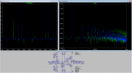
See my previous post, the 10W FFT is actually worst for the 380mA bias then for the 15mA bias. The problem is that at an average of 1Watt you will see lots of signal at up to +15dB.
Optimum bias is to be expected between 20 and 150mA, about 25mV over the output Re's is a good starting point (25mV / 220mOhm = 113.636363636364mA) (in the model I did use rbias = 165 giving about 117mA)
Hi,
attached is my sim-file.
It´s based on #389, but with stray parameters on all caps and a different sim algorithm.
Up to 0.8V (rms) input voltage it sims well, but from 0.85V on the Spice Error log increasingly lists these messages "Heightened Def Con from x to y".
Its accompanied by spikes on the current through Rmes2 and tthe current mirrrors and distorted collector currents of the CFP drivers.
So far I have no idea what may be wrong with the sim.
Compensating the CFPs didn´t change the spooky spiky behaviour.
@RCruz
CFPs are prone to oscillation due to the driver working as Emitter circuit.
Measurements against the oscillation are small Emitter resistors for the drivers, low-capacitance driver transistors, fast output transistors and cap-compensation.
The combination of 2SD669/2SA1186 and 2SB649/2SC2837 works so well, that even paralleling two of the output transistors is possible without any additional compensation.
Other fast (Ringemitter) transistors like the 2SC2922/2SA1216 should do well also.
jauu
Calvin
Attachments
Hi,
attached is my sim-file.
Calvin, can you please post a complete sim-file including referenced sub-model information not standard for LTspice (like the potentiometer). It would also be nice to have the plot files/specifications included.
Frans.
@RCruz
CFPs are prone to oscillation due to the driver working as Emitter circuit.
Measurements against the oscillation are small Emitter resistors for the drivers, low-capacitance driver transistors, fast output transistors and cap-compensation.
The combination of 2SD669/2SA1186 and 2SB649/2SC2837 works so well, that even paralleling two of the output transistors is possible without any additional compensation.
Other fast (Ringemitter) transistors like the 2SC2922/2SA1216 should do well also.
jauu
Calvin
Cool... more power is welcome
Hi,
the models are those attached to Your file Frans.
The Poti can be omitted with alltogether. Its not used in the sim.
Its just a relic of my Sim basic parameter file which I use as starting point for nearly all of my sims, so I don't need to type it all over again and again.
The poti files may be copied from the LTSpice Yahoo group, as well as many other models, for example a THD-Analyzer for THD over frequency or THD over level.
The mentioned sim was a transitional sim at 1kHz or 10kHz with different sine input levels.
Just probe the currents and voltages around the Bias spreader and output stage to see the spikes and distorted wavefoms coming up at input levels >0.8Vms.
jauu
Calvin
Hi,
unfortunately not yet.
It seems not to be a matter of Frans´current source, as the effect also occurs with a resistor or a simple JFET CCS.
It rather looks to me as a problem of the driver of the CFP starving and eventually cutting off.
Btw. regarding Frans´s sim in #335.
What is the source of the OL-gain-peak at ~40-50MHz?
As the OPamp is compensated it could be a matter of the current source or rather a oscillation of the CFPs.
Somhow using the middlebrook probe in my sim the peak doesn´t occur.
Have the transistor models been changed between #335 and #389?
jauu
Calvin
ps. Joachim, Armin Galm and his son visited me lately. We had a nice entertaining afternoon
Last edited:
- Status
- This old topic is closed. If you want to reopen this topic, contact a moderator using the "Report Post" button.
- Home
- Source & Line
- Analogue Source
- JG´s Nobrainer and Nobrainer Discrete