Hi Mikelm,
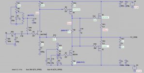
I have 22ohm + 1000UF rail filters on my PCB. I did not redraw Greg's schematics, I just use M$Paint to change some values.
BTW, I am not using any compensating capacitors (C6 & C13) and the amp seems to be stable.
I found that Farnell stocks ZVP2110A (TO92 version) & I will order that to try out. I am running 20mA thru the VAS and the IRP9610 is only luke warm.
Cheers, Stanley
Stan,
The one to get is the zvp2110g, not the a version, as it has a higher power rating. The only problem is that it is a surface mount device which makes mounting a tad more difficult.
If you want to use a to92 device the zvp3310a sounds very good and is cheap from digikey, though the 2110a will probably be even better given its higher transconductance.
With any to92 device you will need to drop the current to 5-10ma, which still seems perfectly adequate.
Do you agree that the 9610 sounds better and better with higher and higher vas currents?
Look forward to your listening impressions with a zetex vas device, whichever one you decide to use.
Last edited:
Mikelm,
Great to hear your positive report. I also found that the distortion of my sig gen is pretty high.
I think, as I mentioned to stan a day or two back, the treble you are seeking will come with replacing the 9610 with a zetex fet, either the 3310 or 2110. The difference is absolutely and immediately noticeable. Also, the dynamics and punch will improve even more.
Kenpeter, your latest is very exciting! JLH style output, which seems to work well with MOSFETs, maybe not so much for BJTs. I would take the bootstrap point from the bottom of D7 so the bootstrap will be more accurate to the 470R G-S resistor on the top, this way the current sharing will be more accurate and Q4 will work less. I think. Although this may be futile the schottkey AB will warp the JLH-effect.
I like the Jfet buffer! Active drive in both directions.
- keantoken
I like the Jfet buffer! Active drive in both directions.
- keantoken
Boscoe
It is in the model library of MultiSim 11.0.1
It is in the model library of MultiSim 11.0.1
.SUBCKT IRFP240 1 2 3
* Model Generated by MODPEX *
*Copyright(c) Symmetry Design Systems*
* All Rights Reserved *
* UNPUBLISHED LICENSED SOFTWARE *
* Contains Proprietary Information *
* Which is The Property of *
* SYMMETRY OR ITS LICENSORS *
*Commercial Use or Resale Restricted *
* by Symmetry License Agreement *
* Model generated on Sep 8, 97
* MODEL FORMAT: SPICE3
* Symmetry POWER MOS Model (Version 1.0)
* External Node Designations
* Node 1 -> Drain
* Node 2 -> Gate
* Node 3 -> Source
M1 9 7 8 8 MM L=100u W=100u
* Default values used in MM:
* The voltage-dependent capacitances are
* not included. Other default values are:
* RS=0 RD=0 LD=0 CBD=0 CBS=0 CGBO=0
.MODEL MM NMOS LEVEL=1 IS=1e-32
+VTO=4.15537 LAMBDA=0.00457587 KP=11.1214
+CGSO=1.21186e-05 CGDO=1e-11
RS 8 3 0.0711966
D1 3 1 MD
.MODEL MD D IS=3.27916e-09 RS=0.010683 N=1.39247 BV=300
+IBV=10 EG=1 XTI=4 TT=0
+CJO=1.2793e-09 VJ=3.00973 M=0.689847 FC=0.5
RDS 3 1 1e+06
RD 9 1 0.0484688
RG 2 7 5.695
D2 4 5 MD1
* Default values used in MD1:
* RS=0 EG=1.11 XTI=3.0 TT=0
* BV=infinite IBV=1mA
.MODEL MD1 D IS=1e-32 N=50
+CJO=2.49691e-09 VJ=0.925116 M=0.9 FC=1e-08
D3 0 5 MD2
* Default values used in MD2:
* EG=1.11 XTI=3.0 TT=0 CJO=0
* BV=infinite IBV=1mA
.MODEL MD2 D IS=1e-10 N=0.402145 RS=3e-06
RL 5 10 1
FI2 7 9 VFI2 -1
VFI2 4 0 0
EV16 10 0 9 7 1
CAP 11 10 2.49691e-09
FI1 7 9 VFI1 -1
VFI1 11 6 0
RCAP 6 10 1
D4 0 6 MD3
* Default values used in MD3:
* EG=1.11 XTI=3.0 TT=0 CJO=0
* RS=0 BV=infinite IBV=1mA
.MODEL MD3 D IS=1e-10 N=0.402145
.ENDS irfp240
.SUBCKT IRFP9240 1 2 3
* Model Generated by MODPEX *
*Copyright(c) Symmetry Design Systems*
* All Rights Reserved *
* UNPUBLISHED LICENSED SOFTWARE *
* Contains Proprietary Information *
* Which is The Property of *
* SYMMETRY OR ITS LICENSORS *
*Commercial Use or Resale Restricted *
* by Symmetry License Agreement *
* Model generated on Sep 8, 97
* MODEL FORMAT: SPICE3
* Symmetry POWER MOS Model (Version 1.0)
* External Node Designations
* Node 1 -> Drain
* Node 2 -> Gate
* Node 3 -> Source
M1 9 7 8 8 MM L=100u W=100u
* Default values used in MM:
* The voltage-dependent capacitances are
* not included. Other default values are:
* RS=0 RD=0 LD=0 CBD=0 CBS=0 CGBO=0
.MODEL MM PMOS LEVEL=1 IS=1e-32
+VTO=-3.63503 LAMBDA=0.00893783 KP=5.11803
+CGSO=1.09348e-05 CGDO=1.38403e-08
RS 8 3 0.0509569
D1 1 3 MD
.MODEL MD D IS=1.17307e-09 RS=0.192326 N=3.5 BV=300
+IBV=10 EG=2 XTI=4 TT=0.0001
+CJO=1.22283e-09 VJ=3.01469 M=0.679605 FC=0.5
RDS 3 1 1e+06
RD 9 1 0.360179
RG 2 7 6
D2 5 4 MD1
* Default values used in MD1:
* RS=0 EG=1.11 XTI=3.0 TT=0
* BV=infinite IBV=1mA
.MODEL MD1 D IS=1e-32 N=50
+CJO=1.08345e-09 VJ=1.0867 M=0.782022 FC=1e-08
D3 5 0 MD2
* Default values used in MD2:
* EG=1.11 XTI=3.0 TT=0 CJO=0
* BV=infinite IBV=1mA
.MODEL MD2 D IS=1e-10 N=0.405431 RS=3e-06
RL 5 10 1
FI2 7 9 VFI2 -1
VFI2 4 0 0
EV16 10 0 9 7 1
CAP 11 10 1.79859e-09
FI1 7 9 VFI1 -1
VFI1 11 6 0
RCAP 6 10 1
D4 6 0 MD3
* Default values used in MD3:
* EG=1.11 XTI=3.0 TT=0 CJO=0
* RS=0 BV=infinite IBV=1mA
.MODEL MD3 D IS=1e-10 N=0.405431
.ENDS irfp9240
Last edited:
Boscoe
It is in the model library of MultiSim 11.0.1
It isn't in mine for some reason and it's the latest one. How do I add that code into multisim?
Stan,
The one to get is the zvp2110g, not the a version, as it has a higher power rating. The only problem is that it is a surface mount device which makes mounting a tad more difficult.
If you want to use a to92 device the zvp3310a sounds very good and is cheap from digikey, though the 2110a will probably be even better given its higher transconductance.
With any to92 device you will need to drop the current to 5-10ma, which still seems perfectly adequate.
Do you agree that the 9610 sounds better and better with higher and higher vas currents?
Look forward to your listening impressions with a zetex vas device, whichever one you decide to use.
Hi Greg,
I received my ZVP2110a today. I chose this one because Farnell got it & free local shipping. I installed it & the first impression was good. The treble sounds livier and the good bass & sweet vocal signature are still there. It is a bit late so I only listen in low volume. I have not done any stability tests.
Cheers, Stanley
Attachments
Great to hear Stan. This is very good news. Many thanks for pursuing this design and raising your soldering iron. How are you feeling about the sound compared to any other amplifiers you have heard?
11mA in the vas is probably a bit much for the zvp. I would drop it to under 8 as your dissipation is quite high for such a small device. Believe it or not, 8mA is plenty enough for the lateral fets and will still drive a near perfect 20khz square wave.
I am especially glad that my listening impressions are being supported by yours given that I have built, fiddled and tweaked with over 10 versions of this circuit, and often was relying on my memory rather than direct a/b tests.
A few hours of run in should improve things further for you.
I would definitely check stability at a range of power levels and loads as the zvp makes quite the oscillator - far less gate/source capacitance and therefore less inherent miller effect. You may need a larger gate stopper and/or a miller cap.
I think now that you are using a sub 1W device in the VAS you might find additional improvement by using a higher q device in the CCS too. One option is a simple BJT ccs using dual BC550 transistors as I have previously posted. It should work very well. Better yet is a simple depletion mode MOSFET ccs.
Well done and keep up the good work!
Hi Greg,
I listened to the Fetzilla (ZVP2110a+IRF610CCS) for a couple of nights.
My Goldmund Mimesis 3 clone (JFET+BJT+Lateral FET) has got silkier treble. OTOH the Fetzilla has fuller bass.
The NS LMe49830 with two pairs lateral FET & higher front end power supply is more detailed but it sounds sterile and dull.
I also had a couple of Blameless amp but they sound boring.
The Fetzilla sounds musical & engaging; it sounds a bit aggressive at high volume. Overall I found that this amp touches all the bases & has the potential for further development. Please note that I only used the passive components that I found in my parts bin & I did not use any exotic parts.
I did two small changes - I bypassed the 0.2R source resistor (I only installed one on the N-FET). I changed the C1 from a 10uF MKT film cap to a 1uF MKP film cap (EPCOS|B32654A6105J|CAPACITOR, 1UF, 630V | element14 Australia) & hopefully it will improve the treble.
I think that the LED+IRF610 is a good stable CCS and I reckoned this will help to stabilize the amp. I had experience with the Goldmund & that amp was under-compensated. I stabilized that amp by changing to transistors with bigger input capacitance on the CCS for the VAS.
BTW, I am running 11mA thru the ZVP2110a and that is not even warm.
I may increase the supply voltage as I am running a higher gain (25x) on mine & in the mean time I just listen & compare with my other amps.
Cheers, Stanley
Last edited:
high gain and low rail voltage makes me wonder if the "aggressive" is simply clipping the output?....The Fetzilla sounds musical & engaging; it sounds a bit aggressive at high volume.............
..............I may increase the supply voltage as I am running a higher gain (25x) on mine
high gain and low rail voltage makes me wonder if the "aggressive" is simply clipping the output?
Hi Andrew,
I guessed that was the cause. I got a 40V PSU but I have to order some suitable capacitors to replace those on the Fetzilla board. I will listen for a while before doing this change. The reason that I used a higher gain because it is hard to do A/B comparison when the other amp has got higher gain.
Cheers, Stanley
wow - my gain is set to 11 ( where clipping becomes impossible with a 2V digital i/p ) and I half the signal before it reaches the amp and I still have to substantially reduce the volume with nearly all media.
Some guys out there must have quite inefficient speakers or must really like to shake the earth
Some guys out there must have quite inefficient speakers or must really like to shake the earth
Some guys out there must have quite inefficient speakers or must really like to shake the earth
Both !!

Watch this - YouTube - 20,000 watt window shake - Tremendous Bass #15
I can only do that from the inside of my house.
Oh , here's them inefficient speakers..
YouTube - meade916's Channel
- I need more ebay amps
OS
With my 6 ohm Jordans this amp in it's current configuration gives almost exactly 10 watts - just like my old JLH simple class A's - but it sounds much more powerful & better, I think in, several different ways. Stanley used the word engaging and this had come to my mind also these last few days.
Perhaps we are witnessing the birth of a Classic.
Perhaps we are witnessing the birth of a Classic.
Hi. My electronics and diy skills are limited (an understatement). I've been following this thread for a while and trying to learn as I read (although most of it is over my head). I had a simple question whose answer is probably obvious to someone with more understanding than me: what is the maximum wattage (4 ohms) that this amp could be configured/built to produce (with proper heat sinking of course)? Thanks.
It depends what rail voltage you decide on with 35 + 35V you could in theory get over 100Watts into 4 ohms - but that would need a stiff power supply and the O/P transistors would probably get a bit over taxed.
35V - 4V lost in VAS stage x .7071 = 21.92V RMS / 4ohms = 5.48Amps x 21.92V = 120Watts !
35V - 4V lost in VAS stage x .7071 = 21.92V RMS / 4ohms = 5.48Amps x 21.92V = 120Watts !
- Status
- This old topic is closed. If you want to reopen this topic, contact a moderator using the "Report Post" button.
- Home
- Amplifiers
- Solid State
- JFET input, MOSFET VAS, LATERAL output = Perfect!!