Resonance and peaking do not cause oscillation. Phase causes oscillation. A negative impedance in parallel with a resonator is an oscillator. Many miller-compensated amps have a negative output impedance at high frequencies because miller compensation does not always compensate properly for capacitive loads. An amp compensated with capacitive loads in mind will show an honest inductive output impedance, and like any normal inductor will resonate with an undamped capacitor. The L/R output network is used on many Miller compensated amps to cancel out their natural negative output impedance. On the other hand sometimes the amp can be compensated in a different way which will make the L/R network unnecessary. However this may decrease performance because you are simply causing the amp to emulate the L/R network.
Most of the time an amp will oscillate into say 1-100nF but be fine into larger capacitors. This is true for modern-style fast amps. In this case it may be effective to add that extra nF of capacitance to the output so the amp will be stable with all loads. However I can't say how this will fare in terms of sonics.
If an amp is stable into 1uF I think it will probably be stable into 100uF. This is because the time constants of these capacitors are too slow to interact with the high-frequency negative impedance regions of the amp's output impedance. However a large capacitor at the end of a coax cable might. This is because an unterminated cable is a resonator. Considering termination, an output L/R might be considered mandatory to avoid the resonant effects of cables. 500nH/50R would work for a 50-ohm coax, as long as it's not long enough to have resonance below 20MHz. This will cause 2.7 degrees 100KHz phase shift for a resistive 6.5R load. Can't say for nonlinear inductive effects though.
I still don't understand this very well though, so don't take my word for it. Please correct me if I'm wrong.
- keantoken
You can have a an amp oscillating even if the output phase margin is okay. But if the phase makes a jump, lets say 20 degreess then there is a great possibility that it will oscillate at the frequence where the phase jumps. Where are talking below 1MHz step for this jump. Just like an ordinary crystal. It can be less or a lot.
NfetZilla the "inverted" version
Hi,
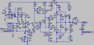
my version of NfetZilla attached. Note the polarity of the supplies !!
1k0 drain load for 2sj74 is currently 500r, drawing ~4.5mA. The device is ~8mAIdss. I will try 330r once I have music coming through. That will increase Id to ~70% of Idss.
Input bias wiper sitting at -2120mV relative to Signal Ground.
Output bias resistor set to ~285r for ~290mA of quiescent bias.
At this higher output bias the drift in output offset is greater. +30mV at cold start up, to -5mV fully warmed up. Varies by +-4mV.
With input shorted the DVM reads -5.1mVdc and 0.0mVac
With the input open circuit the DVM read -5.1mV and 0.1mVac or 0.2mVac.
Sorry, my component numbering is all over the place.
R12, M1 & R13, M3 are swapped. The 300r is on the 2sk1058 and the 200r is on the 2sj162.
Hi,
my version of NfetZilla attached. Note the polarity of the supplies !!
1k0 drain load for 2sj74 is currently 500r, drawing ~4.5mA. The device is ~8mAIdss. I will try 330r once I have music coming through. That will increase Id to ~70% of Idss.
Input bias wiper sitting at -2120mV relative to Signal Ground.
Output bias resistor set to ~285r for ~290mA of quiescent bias.
At this higher output bias the drift in output offset is greater. +30mV at cold start up, to -5mV fully warmed up. Varies by +-4mV.
With input shorted the DVM reads -5.1mVdc and 0.0mVac
With the input open circuit the DVM read -5.1mV and 0.1mVac or 0.2mVac.
Sorry, my component numbering is all over the place.
R12, M1 & R13, M3 are swapped. The 300r is on the 2sk1058 and the 200r is on the 2sj162.
Attachments
Last edited:
The kind of oscillation I described was load-dependent oscillation. This can occur with an amp that has good phase margin, as Sonnya says.
There is more than one cause of oscillation. Miller compensation address only one of these causes. A Zobel addresses the other. One way to avoid needing a Zobel is to decrease open-loop gain.
It sometimes works to increase miller compensation to a very large value, to make an amp stable into capacitive loads. However this will slow the amp down and destroy it's good performance. This is because miller compensation isn't effective for capacitive loads. It is more effective to decrease open-loop gain or use a zobel.
SWF, maybe you could try the amp with capacitors going from 1nF upwards to see what range destabilizes the amp?
- keantoken
As for the design here in this thread, the mosfet is lot better than BJT in handling the capacitive load.
The Zobel network is hard to get around. In my design with 5 pairs of EXC10 i have a bandwidth of 2MHz, and it is stable with an Zobel of 10nF+3.3R (4.8MHz)
Without the Zobel it is not stable, but the Zobel will not load the outputs in the audible range with those values.
The Zobel network is hard to get around. In my design with 5 pairs of EXC10 i have a bandwidth of 2MHz, and it is stable with an Zobel of 10nF+3.3R (4.8MHz)
Without the Zobel it is not stable, but the Zobel will not load the outputs in the audible range with those values.
SWF, maybe you could try the amp with capacitors going from 1nF upwards to see what range destabilizes the amp
He did that already earlier in this thread
. . . . but the Zobel will not load the outputs in the audible range with those values.
but people still report that some amps sound better without zobels so I think we cannot assume it has no audible effect without first testing to see if we can hear a difference
mike
When talking about a Zobel I mean the L/R before the speaker connection. The actual "zobel" has multiple parts, which each need a name. I usually refer to the R+C to ground as a "snubber". When Miller compensation is minimal you can have an amp which is stable into capacitive and low resistive loads, but oscillates into inductors or large resistors.
I think the snubber and L/R network are two different things for the amp. Traditionally a Zobel is used to match impedances. In an amp it is used to aid in stability and may only partially be needed.
I think it may be important to make a distinction between the Snubber and L/R network. I suspect it is the L/R rather than the snubber which some find sonically objectionable? Is this correct?
- keantoken
Member
Joined 2009
Paid Member
Traditionally a Zobel is used to match impedances. In an amp it is used to aid in stability and may only partially be needed.
A Zobel also provides a relatively low impedance to ground for any r.f. signals, if picked up by the speaker cable and so may serve to keep any such signals from entering the amplifier via the nfb network and so reduce the likelihood of their causing issues within the audio band as they encounter non-linear elements. Or so I have read

My understanding is that both a snubber & a zobel can be, and usually are, an RC network.
So what we call a particular RC network should depend upon the intended function.
As someone already said a zobel is used to offer the amp a fairly constant impedance at high frequencies and reduce RF pickup by speaker leads and as such should be placed on the speaker terminals.
A snubber is used to draw in and dissipate amplifier HF ringing / oscillation and is usually placed at the amplifier o/p.
I have heard that some people express the opinion that a "snubber" can detract from the sound ( even though it seems to operate above audio frequencies ) so I believe this should be checked for before including in a design
A zobel, as I understand it is would be employed to attempt to improve the sound so if this desired improvement is not perceptible, it could be argued that it is not worth including.
John Curl says that an o/p choke ( with parallel R ) spoils the sound of an amp and should be avoided if possible.
On one design I worked on, removing the LTP emitter degen resistors seriously improved the overall sound quality even though in theory it should be beneficial to include them.
As globally we are here because we want to enjoy music I think it's a good policy to check the sonic impact of every element in a design before employing it because it "theoretically" helps the situation.
cheers
mike ( the heretic )
So what we call a particular RC network should depend upon the intended function.
As someone already said a zobel is used to offer the amp a fairly constant impedance at high frequencies and reduce RF pickup by speaker leads and as such should be placed on the speaker terminals.
A snubber is used to draw in and dissipate amplifier HF ringing / oscillation and is usually placed at the amplifier o/p.
I have heard that some people express the opinion that a "snubber" can detract from the sound ( even though it seems to operate above audio frequencies ) so I believe this should be checked for before including in a design
A zobel, as I understand it is would be employed to attempt to improve the sound so if this desired improvement is not perceptible, it could be argued that it is not worth including.
John Curl says that an o/p choke ( with parallel R ) spoils the sound of an amp and should be avoided if possible.
On one design I worked on, removing the LTP emitter degen resistors seriously improved the overall sound quality even though in theory it should be beneficial to include them.
As globally we are here because we want to enjoy music I think it's a good policy to check the sonic impact of every element in a design before employing it because it "theoretically" helps the situation.
cheers
mike ( the heretic
)
Last edited:
As globally we are here because we want to enjoy music I think it's a good policy to check the sonic impact of every element in a design before employing it because it "theoretically" helps the situation.
cheers
mike ( the heretic
I agree on that. But if the amp is prone to oscillation in the SIM, it is most likely to be the same in real world. And that have to be fixed in one of the following ways.
1) Minimize the influence of the Zobel and if present LR series.
2) Or redesign the amp, so that they can be removed or at least minimized.
With 10nF it will load the amp with z=159R and 100KHz, and z=795R at 20KHz.
If this impacts the sound, then there is something seriously wrong....
Bigun, that argument would make sense, but I think it depends on the strength of the signal. Typically I don't see anything above 5mV on my 20MHz scope (said to be useful to 100MHz). This is a high-impedance connection at the input. I wouldn't expect an amp to even flinch at these levels especially at it's output, unless it was especially sensitive or you were living next to a transmitter. I could understand if the interference was interacting with sensitive internals such as the VAS directly, especially if these devices had poorly managed local parasitics. However in an amp that doesn't show wild phase or resonance behavior I don't think it should be a problem. It is worth mentioning that an improperly terminated coax cable can resonate and intensify signals at it's resonant frequencies. If the speaker coil has negligible impedance at RF, then a zobel would work at it's terminals. Say 220pF+75R. This will terminate reasonably for cables which are not long enough to resonate below 20MHz (although better if you know the actual impedance of the cable, such as 50 or 75 ohm coax). However the crossover may ruin this depending on it's design.
If speaker cable is not coax but two wires with arbitrary spacing, termination might not be appropriate because what you have is an antenna.
I must say I've never read an explanation of cable termination, whether it's required at both ends or just one, and in general how it works. I only know many people do it, for vague reasons having to do with signal integrity. I'd appreciate it if someone can provide a good link.
- keantoken
 There are plenty of charred amps built by trusting souls who thought stable zero signal conditions existed in working amplifiers. A certain UK builder of small, black and very expensive amplifiers also thought they would dispense with output coils and trust a WW resistor and their speaker leads to damp ringing and RF ingress, but they forgot that hi-fi shops are often close to roads and heavy RFI. My local shop burned out 2 sets of of very expensive speaker drivers in CB radio days. courtesy of this cavalier attitude. The owner being an audiophile of course, vetoed retrofitting the amplifiers or putting external chokes in line. The local distribution agent recommended moving the business!!
The best place for the Zobel or snubber, if you wish, is right at the output junction of the emitter resistors, with minimal lead length, so that it can snub, rather than tag along as an afterthought. However, as the coil is primarily to damp ringing with capacitive loads, it can go anywhere in the box, usually well away from inputs or feedback wiring. That it helps with keeping out EMI generally is good reason to think twice about eliminating it, particularly if there are precious parts involved,
I don't suggest that you can't design for these components to be eliminated, as Sonny advocates but I haven't seen it and I wonder how this new strategy might also affect sonics.
Of course , if you live in a remote area on battery power alone with no SMPS influences, good luck, enjoy!
The coil cannot be removed in a BJT output stage
Not without a drastic redesign of compensation, at least that is my theory.
- keantoken
Hi Kean,
the Pi version of the Output Thiele Network is shown in post1404.
By convention R18 & C17 (R+C) are referred to as output Zobel.
Thiele showed two versions ot the Output Network.
Both had the series connected L//R.
Version he seemed to show more often had the R+C to ground after the L//R
The other version had the R+C before the L//R.
Cherry went on to show that the two Thiele versions were the limiting values of an infinite range of Thiele Networks.
I decided to try the Pi version since that seemed to offer performance gains from both sides.
I simplify the analysis by looking at near infinite frequency. Treat each capacitor as zero impedance and the inductor as infinite impedance, (yes I know that parasitics enter long before we ever get into the RF band never mind approaching infinity) as an effective HF load
The R'+C followed by L//R" simplifies to R' when no speaker cable is connected and becomes R'//R" when a capacitance exists between the speaker terminals.
The other version of L//R" followed by R'"+C across the speaker terminals shows an HF load of R"+R'" when no speaker is connected and R" when the speaker terminals are connected with a capacitor.
The Pi version shows an HF load of R'//[R"+R'"] when the speaker terminals are not connected and R'//R" when the terminals are capacitor loaded.
Note that at HF all the versions show a basic R as the load. It is that R that helps maintain stability of the amplifier at HF.
Hi, my experience is that you are tempting fate using source followers without an output inductor. John Curls recommendation is an inductor of 1uH. JLH said the only way to do away with the inductor was to use mosfets in a CFP with small sig bipolars along with his favoured 0R22 series resistor in the output lead.
Cheers,
Steve.
Cheers,
Steve.
- Status
- This old topic is closed. If you want to reopen this topic, contact a moderator using the "Report Post" button.
- Home
- Amplifiers
- Solid State
- JFET input, MOSFET VAS, LATERAL output = Perfect!!