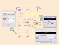
Keep the Zobel and if needed use 1k/100 Ohm solder across terminals as a light load.One annoying thing about the schematic I posted above is that a simple 1nH + 10R zobel on the output would clear that square wave right up and make it behave perfectly well with speakers attached...problem is it's oscillating with no load attached!
Hmm, what on earth is going on?
Is it really an issue anyway given that it won't oscillate with a reasonable load attached?
It's tempting to leave it as is and add a zobel to clean up that ringing and not worry about it!
Low loaded output and oscillation is normal.
Heavy load like 2 or 4 Ohm is more stable than 8 Ohm.
---
Nice current source with DN2530 depletion mode MOSFET
Hi, it's really hard to follow this thread as it progresses and branches out so fast and nice. ")
[OT]
While still waiting for a bunch of P-ch mosfets to arrive to build my own Fetzilla (with BF862 i/p), I had an hour off at work to quickly solder up the probably simplest power amplifier I ever did... as this thread made me think of purposly "sounded" amplifiers more than ever...
Measured not as horrible as I expected, and for the purpose of a tweeter amp (for high efficiency air motion transformer) with high output impedance a first listening test, comparing it to voltage drive from a high feedback elaborated bipolar amp, also had a quite unexpected result, it seemed to sound only slightly different if not better, not the expected grunge of a hell of IMD... I'm sort of confused...
The circuit is inspired by M.J. Renardson's excellent MJR7 amp which I have built a while ago (check out this amp design if not already known), just stripped down to the core and not tweaked in any respect... I'll try find time to try out things the next days...
[/OT]
- Klaus
Attachments
Last edited:
Nice KSTR.
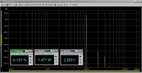
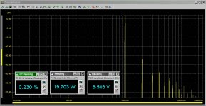
A certain level of THD is only good for health.
And we can consider you circuit having moderate THD at high power output.
This we can not say about my simple circuit.
But for romantic-keep-it-darn-simple it is right.
3 Transistors
A certain level of THD is only good for health.
And we can consider you circuit having moderate THD at high power output.
This we can not say about my simple circuit.
But for romantic-keep-it-darn-simple it is right.
3 Transistors
Attachments
Last edited:
Depletion Mode Fet Model - DN2530
* Supertex depletion mode N channel Mosfet, To92
.MODEL DN2530 NMOS (LEVEL=3 RS=0.25 NSUB=5.0E14 DELTA=0.1 KAPPA=0.20
+ TPG=1 CGDO=3.1716E-10 RD=7.0 VTO=-2.20 VMAX=1.0E7 ETA=0.0223089 NFS=6.6E10
+ TOX=750E-10 LD=1.698E-9 UO=862.425 XJ=6.4666E-7
+ THETA=1.0E-5 CGSO=2.50E-9 L=3.0E-6 W=59E-3 KP=12E-6 Mfg=Supertex-To92)
*
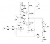
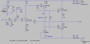
Stable at last
All,
Here it is, stable as the titanic on a lake.
Turned out it was the VAS gate stopper....thanks mikelm!
Miller cap not completely necessary but it does tidy it up a bit. Driving 100nF causes just the tinest bit of overshoot, not enough to concern me.
Sounds very good!
All,
Here it is, stable as the titanic on a lake.
Turned out it was the VAS gate stopper....thanks mikelm!
Miller cap not completely necessary but it does tidy it up a bit. Driving 100nF causes just the tinest bit of overshoot, not enough to concern me.
Sounds very good!
Attachments
Well that particular fix wasn't really my idea but it's great that you finally did it.
I look forward to hearing you subjective assessment etc.
I do hope it works with lead compensation instead of miller.
I will test my board as a preamp today and then add the o/p devices.
mike
I look forward to hearing you subjective assessment etc.
I do hope it works with lead compensation instead of miller.
I will test my board as a preamp today and then add the o/p devices.
mike
Mike,
With 33p of Miller cap and no phase lead, phase shift at 100KHz is 5.8 degrees and margin at 0dB loop gain (1MHz) is around 94 degrees.
With no Miller cap and 47p of phase lead, phase shift at 100KHz is 64 degrees and margin at 0dB loop gain (1.36MHz) is around 78 degrees.
These are both taken with identical 8R resistive load, no cap.
I think maybe the Miller (lag) compensation is the go......
Greg, do you have a model for the ZVP2310A? I've been using the IRF9610 until now and my results are based on that model which incidentally can be used without a heatsink on up to 36V rails.
Hugh
Last edited:
Hugh, Mikelm, Kean,
Thanks both for your support over recent weeks and your advice.
As I mentioned, the amp is quite stable with no miller cap. I added it because it seemed like a good idea and did correct the overshoot slightly.
In this case the sonic difference is very small. I'm happy to leave it there I think.
I'm tempted to try less VAS degeneration. But really, there's almost no point. Everything is there. Clean treble, nice mids and punchy bass. It's a winning formula I think.
Hope you guys feel the same way when you finally get to build it.
Congrats!!!
Wait, can't you find another problem? Is it the end...?
Lol, gate stoppers...
How does the sound of this compare to other amps you've heard? Can you describe it? I suppose this will be on my list to build, to get familiar with FETs.
PS, I just finished reworking my headamp prototype, might've built this instead if I had any Jfets.
- keantoken
It's confusing Hugh. Every time I "fix" my headamp it sounds worse! First it sounded a bit harsh but had a warm sound and gave great emotional engagement with bad singers (no joke!). Then I regulated the rails, which improved stability, and most of that went away. Now I changed to faster, more sensible outputs, and it sounds very clean but a little too harsh. It sounded best with 2SC4370 outputs, so they probably had the worst specs... Right?
However I've found for my amp, how it sounds depends a lot on my level of relaxation while I'm listening. If I'm tense, it'll sound bad. If I'm relaxed, it'll feed my relaxation. It's definitely a "morning amp", as it sounds best in the morning and gets worse as I get exhausted. So I have to make sure I'm not already fatigued when I listen to assess it.
I have to fix my signal generator before I can do advanced testing, which should help identify and eliminate any ringing on the rails, and add the appropriate base stoppers and snubbers to my amp, which in turn will allow me to lower the compensation, which should make it sound better...
- keantoken
- Status
- This old topic is closed. If you want to reopen this topic, contact a moderator using the "Report Post" button.
- Home
- Amplifiers
- Solid State
- JFET input, MOSFET VAS, LATERAL output = Perfect!!