Hi guys,
been a while since I last participated in this debate. Thought I would upload a little simul from the status of me own little 'chestnut baby'... It's playing and in the words of others: 'Very, very cleanly'...
Cheers
DocO

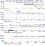
10 micro percent THD at 60V peak, wow!

are you sure this is not the input signal's THD that you are seeing..
Is it 0.00001% (or 0.001%) at 60Vout? Yeah, for this fet topology its too good to be true. But you can still have smaller number if the amp doesn't operate well, e.g. insufficient drive.
Sometimes I think why we should display the chart at all as it is not sufficient to describe the performance of an amp (it is useful for the designer because he know it in conjunction with other numbers). But everyone do it so I do it also
Surprised to see you following the crowd, Jay?
Hugh
Hehe I've simmed and built many circuits (and its derivatives) from this thread. I have been thinking that 3-stage amp is perfect. And I think 0.0001% is the standard of good achievement here. Without the "%", 0.0001% is equal to 0.000001, is equal to 1u THD.
Previous chart shows 10u THD. If that means 0.001% I think it's normal and acceptable. But if that means 0.00001%, it is way too good. Possible, but I don't think it is good sounding.
Yes, I know, we are all seduced by low THD. It is universal, difficult to argue against. But I prefer to examine the harmonic structure, not worrying too much about THD. Perhaps a better measure would be THD for H5 and beyond. That's where I like to see less than 0.001%.
yth,
Hugh
yth,
Hugh
10ppm 2nd harmonic THD @ 80Volts pk
Hi Nico,
it's actually at 80Volts peak.
Don't forget that this is just a microsim, as You so self indicate, but as You also say - microsim is actually amazingly accurate.
I have measured a previous version on an HP35665A DSA (Dynamic Signal Analyzer) I use to own and the real 2nd harmonic for that version was below -80dBs... 3rd just visible above the more than -90dB down instrument noise, with the rest of the 'products' well berried there.
These Sim results are for the improved more stable version and it is playing in real life. There ain't much 'amp-sound' left here, but it has not gone sterile either - just 'Natural Power Fidelity' really...
Currently working on getting a protection system working without to much and many deteriorating effects. This being necessary since StAmp 'thing' is intended for professional use.
All the best
DocO
10 micro percent THD (that is -140 dB) at 60V peak output, besides that it is 2nd order dominant WOW!
Hi Nico,
it's actually at 80Volts peak.
Don't forget that this is just a microsim, as You so self indicate, but as You also say - microsim is actually amazingly accurate.
I have measured a previous version on an HP35665A DSA (Dynamic Signal Analyzer) I use to own and the real 2nd harmonic for that version was below -80dBs... 3rd just visible above the more than -90dB down instrument noise, with the rest of the 'products' well berried there.
These Sim results are for the improved more stable version and it is playing in real life. There ain't much 'amp-sound' left here, but it has not gone sterile either - just 'Natural Power Fidelity' really...
Currently working on getting a protection system working without to much and many deteriorating effects. This being necessary since StAmp 'thing' is intended for professional use.
All the best
DocO
StAmp @ +/-63VDC PSU
Hey chaps,
I did just for fun run a simul with a little less +-63VDC PSU voltages and simple Lateral MosFets out.
Again please - It's just a microsim simulation...
But never the less interesting perhaps?
Best
DocO
Hey chaps,
I did just for fun run a simul with a little less +-63VDC PSU voltages and simple Lateral MosFets out.
Again please - It's just a microsim simulation...
But never the less interesting perhaps?
Best
DocO
Attachments
I am quite surprised of all the activity in this thread. When you start a topic you never know. Most times there are a couple of posts and the thread will die. And nobody cares to build anything of what you show.
It has been my very pleasure to read some of the posts and get report from guys that have built the FETZILLA. It is a rather simple and straightforward circuit. But it works!
Thanks everybody
Special thanks to AKSA who has supported this idea.
It has been my very pleasure to read some of the posts and get report from guys that have built the FETZILLA. It is a rather simple and straightforward circuit. But it works!
Thanks everybody
Special thanks to AKSA who has supported this idea.
I have been developing my DC linked version ( now with DC servo ) of this circuit on & off since this thread began and I continue to be very pleased with the topology. Still have a few more options to test but will present my finished design here once this is complete.
Thx for the idea lineup
Thx for the idea lineup
Mikelm,
I too am working on a DC linked version. Would you care to share your servo arrangement either here or off list? I have devised a simple single transistor servo however it tends to provide some feedback to the input.
I am also working on a version (with some help from some others) which will hopefully have the same sound quality but will deliver 85 WRMS and will not require any fancy jfets, depletion mosfets or vertical mosfets. Hope to post the final version over the coming weeks.
Cheers,
Greg.
Hi Greg,
I'm guessing that my servo is not quite as simple as yours but I am very pleased with how "invisible" it is. Spice predicts that it actually reduced the H10 - H20 noise floor ! but I have not way of telling if that actually happens.
I won't present my circuit here until it is finalised but I'm happy to share with you and discuss our different versions of this cct.
cheers
mike
Mike, the boards are getting made as we speak. Happy to send you some if you can tolerate my style - my PCB design skills are pretty poor!
There's a few people on these forums who will be getting a free set as thanks for their advice and inspiration.
This new version overcomes two of the main shortfalls I see with fetzilla:
1) The limited power capability (the new version is about 85W RMS, not that I ever really need more power but lately I seem to want to play some music quite loudly).
2) The use of rare and hard to find components. This version is all cheap BJTs and Vertical fets.
The design is nothing new, but perhaps a holistic and novel implementation of some old ideas. My initial rats nest sounded quite promising and I am hoping the boards will not disappoint.
When I finally get it made I will post the results in a new thread as it's really not like fetzilla any more except for having three stages with a single ended input and vas.
I have plans to upscale for higher power but that will be my next version in a few months times. I have stayed with jFet i/p for now but in my design it is easy to swap in any i/p device.
My design also does not strictly fit into the "fetzilla" definition because I have mixed up jfets, mosfets, bjt's & laterals. I have the hunch that I will settle for a design with low open loop gain and less FB - I like the relaxed sound this gives.
I'll email you.
My design also does not strictly fit into the "fetzilla" definition because I have mixed up jfets, mosfets, bjt's & laterals. I have the hunch that I will settle for a design with low open loop gain and less FB - I like the relaxed sound this gives.
I'll email you.
Hi Hugh,
I remember you posted somewhere a while back that, after much investigation, the bog standard i/p, VAS & follower o/p topology actually gives very good / best linearity.
I have found that with careful design around this very simple fetzilla topology ( as opposed to exclusive use of MF ) that very nice distortion "profiles" can be realised with very little feedback.
Based on my experience so far I think this may be the way to go.
Currently I'm exploring how much different PSU arrangements and specifically PSU o/p impedance impacts the final sound. I'm suspecting that there will be a sweet spot somewhere between 0.001R & 0.1R that gives a good balance between great detail & imaging and a nice relaxed sound.
For some reason I like the idea of a fairly tightly regulated supply followed by a low FB amp.
any thoughts on this ?
Hugh,
Great to have you back posting on the forums. I knew that post of Mike's would spark your interest! I also agree with the low OLG approach for most types of music and the notion that the basic three stage fetzilla style topology is ideal. In fact, as you know it nearly destroyed my interest in DIY amplifiers because no subsequent topology I have attempted has been as versatile.
One place I think it falls down is in complex music with massive punchy transients. When I can have punchy, competent, liquid, detailed and smooth all in one I will be content. Haha, not likely huh?
Will send you an email soon, good to have you back!
When I can have punchy, competent, liquid, detailed and smooth all in one I will be content. Haha, not likely huh?
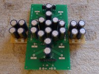
I'm hoping that a low impedance supply will help with this. Right now I'm working on passive supplies but active supplies are designed & waiting to be built.
Here's my latest effort on the passive front:
Attachments
- Status
- This old topic is closed. If you want to reopen this topic, contact a moderator using the "Report Post" button.
- Home
- Amplifiers
- Solid State
- JFET input, MOSFET VAS, LATERAL output = Perfect!!