I plan to build something like that
1) I have no recent experience in building an amp but reading various threads here this one apeals to me
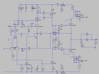
with: CCS in input stage 5 mA (I have 7mA k170 this should be ok) but curent can be adjusted
VAS: 20mA seems to give good results in spice at 1MHz
and DC servo +/- .4volts DC on input compensated (and temperature drift)
not shown on schematic: I would put an optotriac between the collectors of BJT,the triac will short the input stage PSU (with PTC resistors) to turn off the amp in case of abnormal DC at output
...52 volts on input stage 40 volts power stage
comments and suggestions apreciated
Paul
1) I have no recent experience in building an amp but reading various threads here this one apeals to me
with: CCS in input stage 5 mA (I have 7mA k170 this should be ok) but curent can be adjusted
VAS: 20mA seems to give good results in spice at 1MHz
and DC servo +/- .4volts DC on input compensated (and temperature drift)
not shown on schematic: I would put an optotriac between the collectors of BJT,the triac will short the input stage PSU (with PTC resistors) to turn off the amp in case of abnormal DC at output
...52 volts on input stage 40 volts power stage
comments and suggestions apreciated
Paul
Attachments
Hi Paul,
I have also added a servo to my DC linked version of this amp but I found that some of the amp's lovely transparency was lost.
In spice analysis I could see that the servo was causing a significant rise in the H10 - H20 noise floor and also LF HD had increased a lot . . . so I reduced LF 3db point to an extremely low value - about 0.01Hz !
This restored the transparency & low bass definition and made the DC servo sonically quite transparent.
With the gain value you have chosen I'm not even sure that you need a servo but if you decide to keep it I would check out the sound before you add it and then adjust the servo design to make it sonically invisible.
good luck
mike
p.s. The i/p stage ccs
With a ccs in the i/p stage I found the sound was softer and less immediate than with a simple resistor there. At different stages in the development of the design I preferred the sound with the ccs but eventually I chose to revert to a simple resistor.
explaination:
Initially, When I tried the i/p stage ccs I had some very nice resistors in the FB network and standard metal film in other places. Using and i/p stage ccs greatly increases the open loop gain so the status of the FB circuit becomes more significant so the expensive resistors used in the feedback cct gave an improvement in sound.
Later, when I had changed every resistor in the circuit to a high spec ( caddock ) resistor, I found that the advantage I had noticed previously with i/p stage ccs was no longer apparent so I reverted to a simple resistor in the i/p stage.
With same type of resistor in all positions the simple resistor sounds better ( imaging & clarity )
hello mike
thanks for your advice, I apreciate it
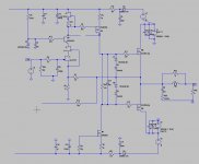
I did more simulations and yes there is no need to have a servo to compensate the VAS thermal variations
my concern was then with input stage (you will notice the values of FB resistors, inspirend from Pass lab F5) so I added another cascode, the J111 in an atempt to have the same voltage across both K170 JFET > same dissipation and hopefully they will compensate each other's thermal drift wich should not be too important as they run near IDSS.
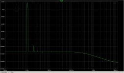
AND IT IMPROVED A LOT THE FFT ANALYSIS IN SPICE, phase margin, no need for compensation cap!
for the last month I simmed many amps and this one is the best!
now how does it sound? hoping that spice is a good start....
I tried with a resistor and no i/p stage CSS and it's not so good for stability and FFT...
it's easy to try both anyway
thanks for your advice, I apreciate it
I did more simulations and yes there is no need to have a servo to compensate the VAS thermal variations
my concern was then with input stage (you will notice the values of FB resistors, inspirend from Pass lab F5) so I added another cascode, the J111 in an atempt to have the same voltage across both K170 JFET > same dissipation and hopefully they will compensate each other's thermal drift wich should not be too important as they run near IDSS.
AND IT IMPROVED A LOT THE FFT ANALYSIS IN SPICE, phase margin, no need for compensation cap!
for the last month I simmed many amps and this one is the best!
now how does it sound? hoping that spice is a good start....
I tried with a resistor and no i/p stage CSS and it's not so good for stability and FFT...
it's easy to try both anyway
Attachments
hello Jay
I am beginer, reading here what other people do and trying to imagine something
what is wrong with the input stage?
As Mike said you can get rid of the cascade. It visually doesn't look "fine" to my eyes (I don't even like even one cascade unless the voltage rating enforces it). And the input stage performance is reflected on the FFT chart. Have you simmed others' circuits (such as Hugh's or Greg's)? You can use them as a benchmark.
My current version of this amp is running in 1A bias in o/p stage with +/- 25V rails for o/p
Stepped down to about 24V for the i/p & vas stages.
For my speakers & tastes this is more than enough power and these voltages mean that I do not need any cascodes ( but have left myself the option of trying one on my board ).
This amp sounds so good you really won't be worrying about any issues you might intellectualise.
now CCS or not CCS that is the question!
very easy to try both - let ur ears decide.
If it were me going for i/p stage CCS I would ramp the current up to about 10mA - this minimises the HF current lag which I think is responsible for the softer sound.
Also . . . although you might like the look of no miller cap in practice I preferred the sound of 30pF - just thought I'd mention it
")
Yes, Mike, same here, I prefer 33pF.......
PaulV,
An amp can be a test mule for all kinds of cool ideas, but as a general rule I've found that simple is better for sound quality, which is why most amps are built. Sound quality rules for most, but there are experimenters who like wild and wacky topologies, and that clearly is necessary to advance the craft, but doesn't always sound good.
Hugh
Cat among the pigeons?
Hi guys,
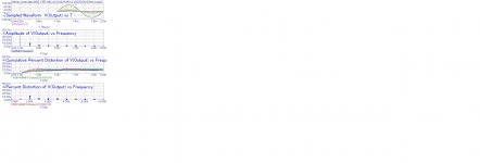
been a while since I last participated in this debate. Thought I would upload a little simul from the status of me own little 'chestnut baby'... It's playing and in the words of others: 'Very, very cleanly'...
Cheers
DocO
Hi guys,
been a while since I last participated in this debate. Thought I would upload a little simul from the status of me own little 'chestnut baby'... It's playing and in the words of others: 'Very, very cleanly'...
Cheers
DocO
Attachments
More cats?
Hi Mikelm,
my circuit is really a bit of this thread topic...
It uses an input LTP for starters in order to ensure minimum offsets with temperature as one of the benefits for starters...
For purity, a single J-Fet is a nice notion, but as can be seen through how this tread has envolved over time, will need additional circuitry in order to optimise for various working wishes and conditions. It can however due to it's signal path simplicity have remarkable sonic performance.
All the best
DocO
Last edited:
2N5551?
Hmmm - at the voltage it can work at, with the given performance, it is actually quite a remarkable device especially together with it's very close equivalent 2N5401...
One could be very tempted to describe it/them as a 'classic(s)'?
All the best
DocO
PS: Needless to say really - device still used a lot in modern constructions - by me included...
My basic conclusion is the most important factor is the actual transistor. It has to be very fast. RF fast. Models lie a lot, if you even have them. I will be ordering a pile of faster transistors for test. After 40 years, someone has bound to better the 2N5551!
Hmmm - at the voltage it can work at, with the given performance, it is actually quite a remarkable device especially together with it's very close equivalent 2N5401...
One could be very tempted to describe it/them as a 'classic(s)'?
All the best
DocO
PS: Needless to say really - device still used a lot in modern constructions - by me included...
Last edited:
Hi guys,
been a while since I last participated in this debate. Thought I would upload a little simul from the status of me own little 'chestnut baby'... It's playing and in the words of others: 'Very, very cleanly'...
Cheers
DocO
10 micro percent THD (that is -140 dB) at 60V peak output, besides that it is 2nd order dominant WOW!
are you sure this is not the input signal's THD that you are seeing. Mind you I trust MicroCap also.
Last edited:
- Status
- This old topic is closed. If you want to reopen this topic, contact a moderator using the "Report Post" button.
- Home
- Amplifiers
- Solid State
- JFET input, MOSFET VAS, LATERAL output = Perfect!!