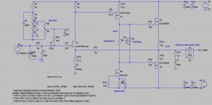
Current working Diagram
The DC drift is definetly better with the i/p stage CCS fitted.
I think I could adjust it to stay within +&- 50mV ( excluding the 1st 60 seconds )
If I stay with this design I would add a DC servo - it gives more design flexibility.
To improve the drift look at temperature compensating the ccs feeding the vas.
As to stability these type amps perform better using only lead compensation, with BJT vas anyway although I dont see why it wouldnt be the same with mosfets. Look at Mooly s amp as an example.
Thank you both for your suggestions.
I agree that lead compensation seems to work better but despite this I think I preferred the sound of lag - I will go back & check again because the design has changed a bit since then - this design needs about 5pF Lag for basic stability having applied that I can choose which I prefer.
The amp works OK with or without o/p snubbers - I will do a subjective test to see which I prefer soon
cheers
mike
Last edited:
Wow, I sat down to listen to a single song today and here I am 5 hours later still listening after working through tons of CDs. No amplifier I have ever heard sucks you in like this one. It has enough engagement to draw you into the music and yet enough detail that you can sit and pull the music apart for hours on end.
I keep looking for more complicated circuits that "must sound better", but I keep getting drawn back to this one and its measly 5 transistors. Amazing.
I keep looking for more complicated circuits that "must sound better", but I keep getting drawn back to this one and its measly 5 transistors. Amazing.
") Nice to hear that Greg - can you remind us of ur final version.
Nice to hear that Greg - can you remind us of ur final version.I am also delighted with the sound I am getting - it's now been playing in the living room and I have been amazed - I never heard anything like it.
So I think we can also say that this design concept can be adapted to suit everyone's tastes.
After a few more finishing touches - when it really looks like a finished circuit perhaps I will begin a thread to formally present it - may be a little while though.
mike
BTW, I should mention that I measured the DC offset today, as I haven't for some time.
Within one minute of turn on it was within a few mV. Five hours later each channel was at exactly 6mV. I haven't made any adjustments since I set it up several months ago.
The amp is simple, cheap and rivals the best, though some of the parts are hard to come by. If you're out there contemplating a Hiraga or JLH class A, I say build this instead. Within its power ratings it is exceptional.
Yep, I played around with all sorts of compensation and ultimately preferred having no compensation and dropping the OLG by using the humble ZVP3310A. That said, I didn't find phase lag comp too detrimental. Wasn't a big fan of phase lead though.
The amp is unconditionally stable without any compensation or output choke though it suffers from overshoot. This is corrected by using a large output choke. The output choke is not compulsory, and in fact the amp sounds very lively and energetic without it. Adding the choke calms things down a bit though, and adds a tubey character IMO.
The amp is unconditionally stable without any compensation or output choke though it suffers from overshoot. This is corrected by using a large output choke. The output choke is not compulsory, and in fact the amp sounds very lively and energetic without it. Adding the choke calms things down a bit though, and adds a tubey character IMO.
I think the highlight of my day is when I bring one of the guys from work home for a listen.
They're all cashed up with their big lifeless 7.1 surround sound systems. I play some Melody Gardot and they always say something like "I can't believe you can build something like that. How does it sound so good? It sounds like she's in the room. How can it have so much bass with only 6" speakers and no sub?".
Sorry to rant, I've just had quite the perfect day. Waterskiing in the morning followed by perhaps the most rewarding listening session I've had. Haven't even turned the amp on in months due to being so unbelievably busy.
Actually, in all my sims using a ZVP3310a for the VAS increased OLG compared to a BJT.
True, but I was talking about relative to other mosfets!
This circuit sounded shocking with a BJT VAS and JFET input in my opinion. A BJT input and VAS was OK though.
Congratulations, Greg. Good sound takes a long time to achieve, and most large corporations don't even get close. You've got there damn quickly.....
Hugh
Couldn't have done it without the good advice offered by people such as yourself on the forums!
Hi Mike, all,
I'm looking to build a DC version of this amp, and have a couple of questions. First how critical is the current through the input transistor? Would it be possible to make a CCS that has an inverse tempco to the JFET, stabilizing DC drift? Also, how does one adjust offset?
Thanks,
Dan
I'm looking to build a DC version of this amp, and have a couple of questions. First how critical is the current through the input transistor? Would it be possible to make a CCS that has an inverse tempco to the JFET, stabilizing DC drift? Also, how does one adjust offset?
Thanks,
Dan
Well, as you may have noticed I have replaced the i/p stage resistor with a 2sk170 based CCS. This does help to stabilize the DC drift but whether or not that will be low enough to satsify you I'm not sure.
Also this arrangement does significantly increase the OLG in the audio band which changes the sound - to my ears that change is for the better. At frequencies where stability issue arise the OLG is unchanged so compensation can be left unchanged - perhaps with a minimum of 10pF - I think 30pF sounds best
To change the offset the CCS value can be adjusted with a trimmer. . . .
However, my ultimate version of this amp will probably end up having a very carefully implemented DC servo but NOT because I am unduly worried about the DC offset levels. . . .
In the development of this design I gradually changed over from standard metal film resistors to Caddock TF020 or MK132's. Each upgraded resistor brought a noticeable change in audio quality and significantly even more of a change was heard when trimmers were replaced with these high quality fixed value resistors.
To enable me to entirely eliminate trimmers from the "Audioband" part of the circuit I am planning to consign my DC offset trimmer to the servo circuit which will operate well below the audio band thus, I hope, making it sonically invisible.
I Hope you enjoy the sound of the DC linked version as much as I do. It seems to be extremely revealing and quite forgiving all at the same time.
Hope some or all of this helps
mike
Last edited:
Thanks, that's helpful Mike. I'll build it with a trimmer in the CCS. I guess the high OLG version sounds cleaner and less "romantic", hopefully it doesn't lose the charm.
Earlier you said that you had to use a particular earthing arrangement, could you say more about that? This is my first veroboard amp, so I'm having to work out these details as best I can.
Earlier you said that you had to use a particular earthing arrangement, could you say more about that? This is my first veroboard amp, so I'm having to work out these details as best I can.
Yeah - very clean and quite romantic - that's a good description
I make every effort to keep the earth as clean as possible. As the earth is common throughout the system these measures have to be applied everywhere to gain maximum effect. I use differential & common mode chokes on all of my supplies to achieve this.
I make every effort to keep the earth as clean as possible. As the earth is common throughout the system these measures have to be applied everywhere to gain maximum effect. I use differential & common mode chokes on all of my supplies to achieve this.
The 2SK/2SJ pair certainly are rare now, but maybe these could work as an alternative:
Mosfets/Modules - Lateral MOSFETs - Class D
or
ECX08N16-Z
ECX08P16-Z
These seem to be readily available laterals. Your first circuit modelled as very nice performance.
A bit late to the party, but,
I put the Exicons in my Hafler 120. It took quite a bit of work to get it stable. Basically totally redoing the compensation. ( VAS loading to TMC) The model is higher distortion than the Hitachi model, but I don't know reality yet. The Exicon's are faster had have half the gate capacitance.
I spent the last week playing with ccs models. ( about 20 typologies) The basic BJT-LED is darn good. A really fast FET is more linear. Fet-cascode stiffer. The FBP seems popular in VAS, It is also pretty linear but not as stiff. Those three seem to better all the other typologies.
My basic conclusion is the most important factor is the actual transistor. It has to be very fast. RF fast. Models lie a lot, if you even have them. I will be ordering a pile of faster transistors for test. After 40 years, someone has bound to better the 2N5551!
- Status
- This old topic is closed. If you want to reopen this topic, contact a moderator using the "Report Post" button.
- Home
- Amplifiers
- Solid State
- JFET input, MOSFET VAS, LATERAL output = Perfect!!