Hi Choky, YGM... You got Mail. Look for a message from me to your DiyAudio email.
I'm planning on wiring it up and testing it. Just would like some more confirmation on the design. It would be great if someone had a spice sim.
I run balanced all the way, both sides source and amp.
-David
I'm planning on wiring it up and testing it. Just would like some more confirmation on the design. It would be great if someone had a spice sim.
I run balanced all the way, both sides source and amp.
-David
dw8083 said:Hi Choky, YGM... You got Mail. Look for a message from me to your DiyAudio email.
............
-David
I know.......JJ
just jokin'
")
YT
Zen Mod said:
I know.......JJ
just jokin'
YT
ARRGH! That's the second time you've pulled my leg! I forget your sense of humor.
You make this board fun.
-David
Hi,
just a few remarks/ questions:
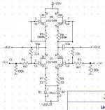
you have 20dB of gain (2k2 /22k). This is a bit high for a preamp (even if you want to mate it with an F4)
The value of R5 and R6 can be calculated so the output sits at aproximately 10-11V (half the supply voltage)
The 100k´s could be moved to the gate again
Why use 2sk389 for the current sources?
William
just a few remarks/ questions:
you have 20dB of gain (2k2 /22k). This is a bit high for a preamp (even if you want to mate it with an F4)
The value of R5 and R6 can be calculated so the output sits at aproximately 10-11V (half the supply voltage)
The 100k´s could be moved to the gate again
Why use 2sk389 for the current sources?
William
Zen Mod said:
btw- do you have them,and what's the price there?
I remember Linear System was kind enough to send me 5 pieces of LSK389 as samples
stefanobilliani said:
I remember Linear System was kind enough to send me 5 pieces of LSK389 as samples
hehe
they don't think in stereo sets?
they charge for shipping,naturally?
wuffwaff said:Hi,
just a few remarks/ questions:
**you have 20dB of gain (2k2 /22k). This is a bit high for a preamp (even if you want to mate it with an F4)
***The value of R5 and R6 can be calculated so the output sits at aproximately 10-11V (half the supply voltage)
The 100k´s could be moved to the gate again
Why use 2sk389 for the current sources?
William
** really depends ; more mater of taste and need -you're right-easy to change with just pair of resistors
***and where needed current for lower CCS will pass,if you choke upper 389 (upper CCSes)?
R5 and 6 must be set for current sum
This is very interesting!
I'm afraid I'm not into electronic design very much so cannot contribute with any comments about the schematics, but I'm thinking about trying to build one.
Which type of LSK389 would be suitable for the schematics posted, type A, B or C?
I hope you can excuse my ignorance.
/Fredrik
I'm afraid I'm not into electronic design very much so cannot contribute with any comments about the schematics, but I'm thinking about trying to build one.
Which type of LSK389 would be suitable for the schematics posted, type A, B or C?
I hope you can excuse my ignorance.
/Fredrik
trango said:This is very interesting!
I'm afraid I'm not into electronic design very much so cannot contribute with any comments about the schematics, but I'm thinking about trying to build one.
Which type of LSK389 would be suitable for the schematics posted, type A, B or C?
I hope you can excuse my ignorance.
/Fredrik
current is important.
B or ,even better,C
btw-nobody is born smart......
so-just chill
Zen Mod said:
hehe
they don't think in stereo sets?
they charge for shipping,naturally?
heheh
no it was complitely free , shipping includedwuffwaff said:Hi,
just a few remarks/ questions:
you have 20dB of gain (2k2 /22k). This is a bit high for a preamp (even if you want to mate it with an F4)
The value of R5 and R6 can be calculated so the output sits at aproximately 10-11V (half the supply voltage)
The 100k´s could be moved to the gate again
Why use 2sk389 for the current sources?
William
Hi William,
What would be your suggestion for values R1-R4, If the gain is too high?
I used the LSK389 for the current source I had them already. But you are right a mosfet or something else could be used. If you would like to suggest a better part, I'm open to ideas.
Thank you!
-David
dw8083 said:
Hi William,
What would be your suggestion for values R1-R4, If the gain is too high?
I used the LSK389 for the current source I had them already. But you are right a mosfet or something else could be used. If you would like to suggest a better part, I'm open to ideas.
Thank you!
-David
ratio 2k2/22k gives you gain
make it 4k7/22k to halve it
for CCSes (both upper and one lower) you can use whatever you want.........but-stay with LSKs if that suits you,or make two BJT CCSes .........as in Babelfish,for instance.
boyz at toob forum are frenzy with LED referenced CCSes ,but I have no any valid link handy in this moment.
anyway- I'll choose CCS a la Babelfish before LSK one ; both- cheaper and better
hehe-and just for fun-when you going to make final version,make shunt regs for both sides
Babowana said:>>O<<
Hey schematic, post#29, forgive me for my question.
How are you going to work with no input coupling cap?

you're dumb almost as Serb ..........

gates are referenced to gnd via 100K resistors
i REALY LOOK AT OTHER THINGS,PRdamn caps lock.....esuming that schematic is almost correct;
this way it will work
R5 and R6 really needs trimming - to achieve 4,7 mA through each half of upper LSK, and this way- as in every proper susy ,output caps are included in fdbck loop........theoretically killing cap induced nasties (if any) through susy effect
Attachments
Zen Mod said:you're dumb
Heh . . . ^db^
Hey! Schematic above! Only two questions.
What is going to be your voltage gain? 100/33 < 22K/4.7K
You really going to waste potential thru D1 and D2?
Babowana said:
Heh . . . ^db^
Hey! Schematic above! Only two questions.
What is going to be your voltage gain? 100/33 < 22K/4.7K
You really going to waste potential thru D1 and D2?
re-read my previous post
100 will not be 100,they mmust be trimed for current of 4,7mA
D1 and D2 are CCSes-where is waste?
I have thought R5 and R6 as too low.
And, -22V minus few voltages will be used across D1 and D2.
How about introducing the input coupling caps and using
only +rail? If so, we could use lower V across D1 and D2,
and could have bigger R5/R6. Then, the voltage gain will
follow the value of 22K/4.7K . . .
Don't take this seriously. Just an opinion ^^.
Babowana said:I have thought R5 and R6 as too low.
And, -22V minus few voltages will be used across D1 and D2.
How about introducing the input coupling caps and using
only +rail? If so, we could use lower V across D1 and D2,
and could have bigger R5/R6. Then, the voltage gain will
follow the value of 22K/4.7K . . .
Don't take this seriously. Just an opinion ^^.
I have no graphs for LSK and I can't know values of R5 and R6 for 4,7mA without graphs and without LSKs on my bench
they're there as CCSes,so I can't see connection between values of R5 and R6 and overall gain
degeneration resistors in sources of "active" (lower) LSK will have influence on OLG,certainly.
anyway-without graphs I can't tell most adequate voltage for plus and minus PSUs,but I presume that these voltages are good starting point.
you can always choose single sided supply ,as you say-implementing caps on inputs,moving 100K resistors away from gates......
why not-if that's your Zen.........
you know that I don't take seriously anything..........
The input to the design is great!
I'm thinking of builting an integrated amp with my Aleph30. I thought I'd take advantage of the negative voltage, since it is there already.
The first batch of parts arrived today. Time to finish the design, and gas-up the soldering iron.
-David
I'm thinking of builting an integrated amp with my Aleph30. I thought I'd take advantage of the negative voltage, since it is there already.
The first batch of parts arrived today. Time to finish the design, and gas-up the soldering iron.
-David
The input to the design is great!
yeah, I don't think Choky and Bobo ever get to build anything themselves, their too busy helping everyone else out!
(no I didn't expect you to build it choky! Didn't I see you with some Krell clone PCB's?)
If you are going to use this with an Aleph 30, you might take a look at increasing the source resistance to reduce the gain. (I am assuming you are using this with a CD player not vinyl).
The BOSOZ has lower distortion with reduced gain (if you reduce the gain by adding source resistance, that is.) This circuit, I think, is more like an Aleph "J"P -- I am not sure if the aleph P also has lower distortion with more source resistance -- maybe one of the gurus out there can confirm.
Anyway, if your CD player is putting out 2 volts, I think you only need about 6dB of gain (if that) to get full output from the Aleph 30. I may have to dig up my tutorial sheet on dB calculations.
The fact that you have balanced sources is a benefit. I saw some problems with unbalanced to balanced conversion with the BOSOZ. But then, this is not really a BOSOZ.
JJ
- Status
- This old topic is closed. If you want to reopen this topic, contact a moderator using the "Report Post" button.
- Home
- Amplifiers
- Pass Labs
- Jfet Bosoz?