If all these systems were perfect, they would sound pretty much the same. However, I am sure in practice these will all sound different. These audible differences are what effect design trade off. I think Pooge is trying to get a feeling what the trade offs are in terms of listening.
Correct. Experience is the best teacher.
The real problem with lots of these listening impressions of these systems is that people don't want to say anything bad about it in an open manner, most are also reluctant to rave about a setting of others as well in case they might loss face when others point out problems. I make an effort to describe the changes heard with exploration of each major issue encountered in development process. Still, it is subjective. I let others compare side by side with other systems and generate their own conclusions since priority of different aspects vary.
Jean-Michel, I don't think anyone said that. Of course your horn will have "less pattern flip", ie control vertical directivity lower than a smith horn (which is something like 5cm high, and uses almost only diffraction in the vertical plan...), but this is not much more than a pure geometrical problem and any horn with similar dimensions to yours will have the same vertical directivity "cutoff".
There is nothing wrong about it: "pattern flip" is just the symptom of a horn used lower than its "vertical cutoff" (lets call it that way...). Some system actually put this symptom to good use, like the JBL Array 1400 for example with a *very* smooth woofer/horn directivity transition.
The horn on the JBL 1400 is about 20cm wide.
1700hz is 20cm wide.
Based on that, I would expect the beamwidth of the horn to broaden as we approach 1700hz, and get wider in the octave below that.
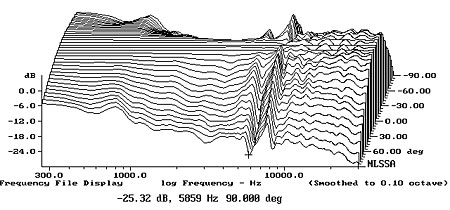
Here's the polar response of the 1400; see how the directivity broadens at 900hz then dips again at 600hz?
That's due to the transition at the crossover point. Basically the horn has a broader beamwidth than the woofer, so there's a bit of a mismatch at the crossover frequency.
I believe that an argument could be made for turning that horn on it's side, which might make for a smoother transition from woofer to tweeter.
Then again, the transition is still quite smooth, and the tall vertical horn looks good.
I'm using a vertically oriented horn for my current project documented in the thread named 'Monster Massive.'
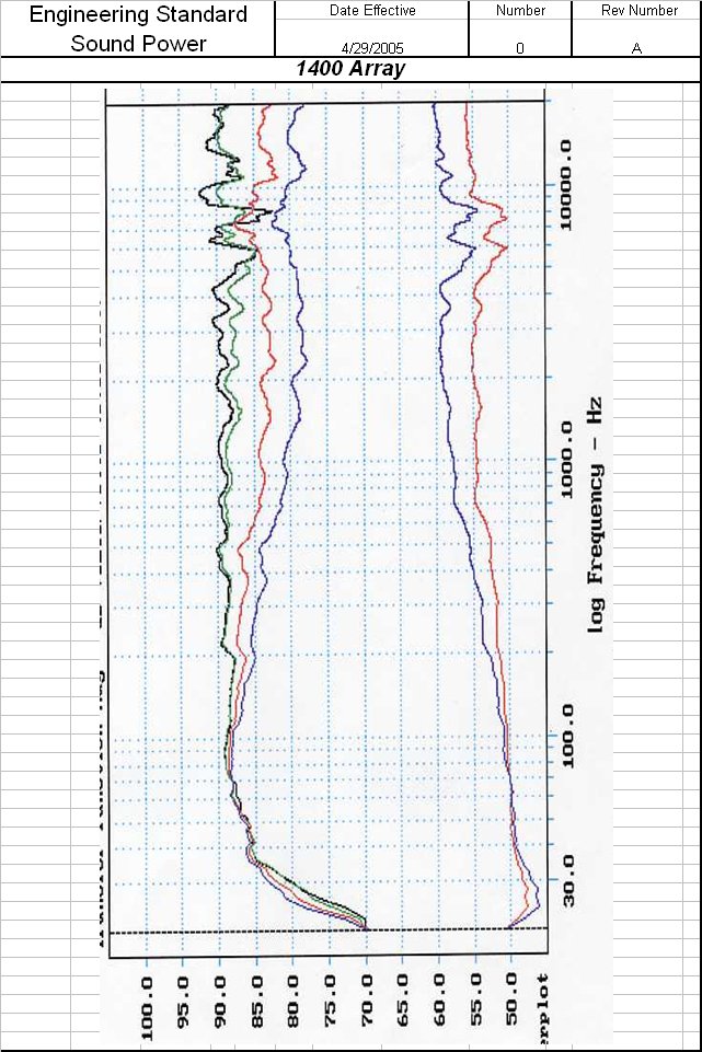
Here is a comparison of the "Tool curves" from JBL engineering sheets for the Array1400 and S9800, both using (almost) the same horn, vertically for the array1400 and horizontally for the S9800.
The array1400 crosses the 14" woofer at 750Hz whereas the S9800 crosses the 15" woofer at 800Hz (with shallower slopes).
Array1400:
S9800:
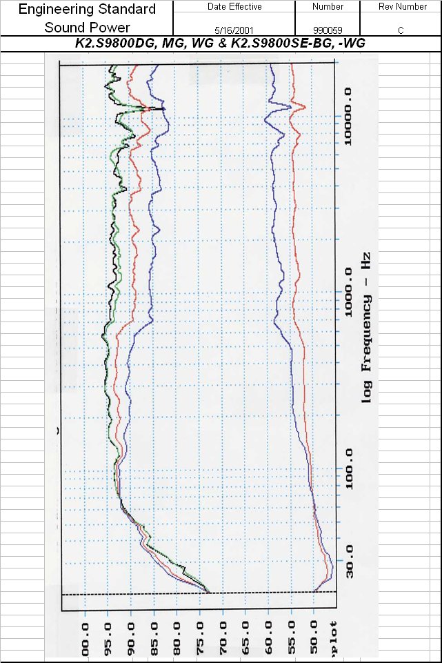
The slow gain in directivity on that horn in the vertical plan matches the behavior of the direct radiator really well, which makes for a seamlessly transition ("listening window curves", second ones after the on-axis, are averaged on 30° horizontal and 15° vertical spans)
The little dip in the power response at the crossover point visible for both speakers is typical of acoustical LR crossovers.
The array1400 crosses the 14" woofer at 750Hz whereas the S9800 crosses the 15" woofer at 800Hz (with shallower slopes).
Array1400:
S9800:
The slow gain in directivity on that horn in the vertical plan matches the behavior of the direct radiator really well, which makes for a seamlessly transition ("listening window curves", second ones after the on-axis, are averaged on 30° horizontal and 15° vertical spans)
The little dip in the power response at the crossover point visible for both speakers is typical of acoustical LR crossovers.
Last edited:
Jean-Michel, I don't think anyone said that. Of course your horn will have "less pattern flip", ie control vertical directivity lower than a smith horn (which is something like 5cm high, and uses almost only diffraction in the vertical plan...), but this is not much more than a pure geometrical problem and any horn with similar dimensions to yours will have the same vertical directivity "cutoff".
There is nothing wrong about it: "pattern flip" is just the symptom of a horn used lower than its "vertical cutoff" (lets call it that way...). Some system actually put this symptom to good use, like the JBL Array 1400 for example with a *very* smooth woofer/horn directivity transition.
Hello Pos,
Do you really think that the transition from woofer to horn is something I don't take in account?
For sure I take this in acccount! If you read Lynn Olson's thread you'll see that the choice he made of the AH425 horn (an axisymetrical Le Cléac'h horn ) is partially done to obtain a smooth transition from the directivity of the bass driver to the horn.
There is a large choice of Le Cléac'h horns (Fc, shape, etc) and you can also design an axisymetrical horn adapted to your need using my spreadsheet or Hornresp, so normally everyone can find a Le Cléac'h horn that can assures a smooth transition of directivity between the bass loudspeaker and the horn.
Best regards from Paris, France
Jean-Michel Le Cléac'h
Jean-Michel, of course I know this is a point you take into account. I am certainly not trying to dismiss your approach here, and I really appreciate your work. I just want to highlight that "pattern-flip" is not some sort of misbehavior that can be fixed with specific profile: it is purely geometrical (and can be described using Webster equations quite accurately). It is something that has to be taken into account (and possibly put to good us as in the array 1400) by either choosing a high enough crossover frequency (as in your example with the E-JMLC 1000) or using round horns as you just explained.
Yes but this would be chosen first and this puts the pattern change out of band. Isn't this like crossing a tweeter at 200Hz and declaring it broken because it doesn't have enough excursion?by either choosing a high enough crossover frequency
"pattern-flip" is not some sort of misbehavior that can be fixed with specific profile: it is purely geometrical (and can be described using Webster equations quite accurately).
Hello Pos,
I don't think that Webster equation is able to do that...
Best regards from Paris, France
Jean-Michel Le Cléac'h
yes of course, my point exactly: nothing inherently wrong with "pattern flip" behaviorYes but this would be chosen first and this puts the pattern change out of band. Isn't this like crossing a tweeter at 200Hz and declaring it broken because it doesn't have enough excursion?
Last edited:
I think the approximation is close enough in this particular case. What alternative model would you use?I don't think that Webster equation is able to do that...
I think the approximation is close enough in this particular case. What alternative model would you use?
Hello Pos,
IMHO Webster's equation cannot be used to predict directivity...
But may be I didn't understand the way you want to use the Webster's equation...
Best regards from Paris, France
Jean-Michel Le Cléac'h

All horn and quasi-optimal crossovers addicts will be very sad to know that Jean-Michel Le Cleac'h won't post anymore :
Notre Grand Ami Jean-Michel Le Cléac'h
 R.I.P. posts moved to: http://www.diyaudio.com/forums/memoriam/304412-rip-jean-michel-lecleach.html
Notre Grand Ami Jean-Michel Le Cléac'h
R.I.P. posts moved to: http://www.diyaudio.com/forums/memoriam/304412-rip-jean-michel-lecleach.htmlFor very large horns Ferguson is better because 1.6m arranged vertically can be used fullrange in room corners with cone loudspeakers.
anyone have an idea - how to be a big horn (for CD) for room corners placement?
Hello Esperado,
Apart the air non linearity at throat that a horn provides due to a large ratio mouth area / throat area, I don't think a horn can bring distortion by itself.
Bad horns and noticeably the ones based on diffraction (waveguides...) may eventually redistribute the distortion components appearing at the throat in more or less discrete directions. BTW the same effect is desired in ultrasonic devices fro which we want them to deliver a thin ultrasonic beams...
It make me smiling when I see people asking for the distortion curve of a horn considered by itself. There is not such. But the way a horn loads more or less resistively and actively a loudspeaker can for sure leads to differences in distortion curves (on the same driver).
As an example, see the measurement I have done at ETF2010
(Measurements performed on 16 horns ... http://forums.melaudia.net/attachment.php?aid=1760 )
from which I extract the measurement of a TAD TD2001 on 2 different horns :
- Le Dauphin sectoral horn
- J321 Le CLéac'h horn.
see how the H2 curves are similar, noticeably around 1kHz. For the J321 measurement, reduced H2 at HF and other H3, H4, H5... components are mostly due that for the measurement performed on my J321 I used (as I always do with a TAD TD2001) a series resistor (30ohms) which one provides a reduction of distortion of the compression driver due to a better "current drive" (see Hawksford paper : http://www.essex.ac.uk/csee/researc...J12 Distortion reduction MC current drive.pdf )
Best regards from Paris, France
Jean-Michel Le Cléac'h
Sorry if it has been said before but what would be the difference in using a 10ohm resistor VS a 30ohm one?
Thank you,
Kelvin
- Home
- Loudspeakers
- Multi-Way
- Jean Michel on LeCleac'h horns