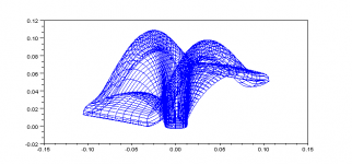
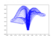
I call it rectangular JMLC horn.
It is calculated by JMLC wave-front expansion method, but with different expansion rate in each direction.
fc 1kHz, 1 inch throat, T=1/sqrt(2).
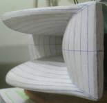
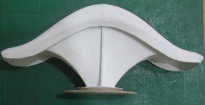
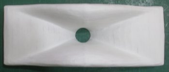
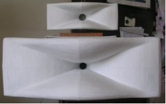
Sample is made by cardboard, and reinforced by wall putty.
It is calculated by JMLC wave-front expansion method, but with different expansion rate in each direction.
fc 1kHz, 1 inch throat, T=1/sqrt(2).
Sample is made by cardboard, and reinforced by wall putty.
Attachments
I call it rectangular JMLC horn.
It is calculated by JMLC wave-front expansion method, but with different expansion rate in each direction.
fc 1kHz, 1 inch throat, T=1/sqrt(2).
Sample is made by cardboard, and reinforced by wall putty.
Great job
")
3D printing should be great if there is possibility for it.
Bicorne
The horn's profile reminds me of Napoleon’s hat.
Have you done any frequency response simulations or actual tests yet?
Regards,
WHG
I call it rectangular JMLC horn.
It is calculated by JMLC wave-front expansion method, but with different expansion rate in each direction.
fc 1kHz, 1 inch throat, T=1/sqrt(2).
Sample is made by cardboard, and reinforced by wall putty.
The horn's profile reminds me of Napoleon’s hat.
Have you done any frequency response simulations or actual tests yet?
Regards,
WHG
Sorry, there is no simulation or test data for it. The BEM program is too difficult to me to understand. I had made some round and elliptic type JMLC horn by the same method, and rectangular type seems more suitable for short distance (< 2 meter) listening.
Attachments
Sorry, there is no simulation or test data for it. The BEM program is too difficult to me to understand. I had made some round and elliptic type JMLC horn by the same method, and rectangular type seems more suitable for short distance (< 2 meter) listening.
XYZ file (unit mm)
1k.xyz 360(degree)*134(points)=48240(points)
500.xyz 360(degree)*125(points)=45000(points)
Attachments
Hello Pos,
Do you really think that the transition from woofer to horn is something I don't take in account?
For sure I take this in acccount! If you read Lynn Olson's thread you'll see that the choice he made of the AH425 horn (an axisymetrical Le Cléac'h horn ) is partially done to obtain a smooth transition from the directivity of the bass driver to the horn.
There is a large choice of Le Cléac'h horns (Fc, shape, etc) and you can also design an axisymetrical horn adapted to your need using my spreadsheet or Hornresp, so normally everyone can find a Le Cléac'h horn that can assures a smooth transition of directivity between the bass loudspeaker and the horn.
Best regards from Paris, France
Jean-Michel Le Cléac'h
I post my rect horn profile here because I think what Jean Michel said is right.
If you know how to calculate his "wave front" surface, you can get almost
any shape of horn you want.
Jean Michel's method is really superior than any other old design method.
I post my rect horn profile here because I think what Jean Michel said is right.
If you know how to calculate his "wave front" surface, you can get almost
any shape of horn you want.
Jean Michel's method is really superior than any other old design method.
Hello there,
Wondering if you would be prepared to share the code used to calculate the elliptical and rectangular JMLC profile? Is it Matlab/Octave?
Best,
cv
Hello there,
Wondering if you would be prepared to share the code used to calculate the elliptical and rectangular JMLC profile? Is it Matlab/Octave?
Best,
cv
Hi cv,
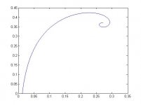
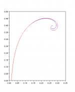
The code is executed on OPEN SOURCE SOFTWARE Scilab.
It is the first and kernel part of the calculation.
The result is a profile of round horn.
I save the profile as a template for subsequent calculation.
You may note that the profile is more different from JMLC's spreadsheet near mouth.
Because I use integration formula to calculate surface.
Please let me know you can run this code by yourself.
It will be easier to explain others codes.
Best regards
Hsieh W.M.
Attachments
Hi WM,
Very kind! That helps a lot; I will try and code this up some point this weekend (never seen scilab before but it seems pretty straightforward).
Will let you know how I get on - seems like a good idea to get the circular form working before attempting the elliptical!
Thanks very much indeed and best wishes,
cv
Last edited:
Hi again,
Bit sooner than promised - I ported code to matlab (almost nothing too it really) and got the attached output.
Looks reasonable to me! It took quite some time to run but I assume that's because of your more refined calculations.
It will take me quite a bit longer to go through the mathematics and understand the code, but all good so far.
Look forward to hearing how the elliptical calculation works; do you basically repeat the circular calculation multiple times for different parameters?
Thanks again, great stuff!
Attachments
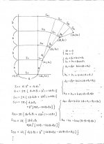
Curvature & Element Issues
For a round section horn I do not see how this departure could be that large, between the elemental approximation and the integral for it.
For other horn boundary conditions, that departure, particularly in the [x,z] plain, would be expected as the controlling area expansion is over an entirely different surface expansion.
Further I note, that the center element shown here as a straight line segment, should be in most cases, an arc bounded by an angle equal to that of the tangent at the compression driver exit.
Regards,
WHG
Hi cv,
The code is executed on OPEN SOURCE SOFTWARE Scilab.
It is the first and kernel part of the calculation.
The result is a profile of round horn.
I save the profile as a template for subsequent calculation.
You may note that the profile is more different from JMLC's spreadsheet near mouth.
Because I use integration formula to calculate surface.
>snip<
Best regards
Hsieh W.M.
For a round section horn I do not see how this departure could be that large, between the elemental approximation and the integral for it.
For other horn boundary conditions, that departure, particularly in the [x,z] plain, would be expected as the controlling area expansion is over an entirely different surface expansion.
Further I note, that the center element shown here as a straight line segment, should be in most cases, an arc bounded by an angle equal to that of the tangent at the compression driver exit.
Regards,
WHG
Last edited:
For a round section horn I do not see how this departure could be that large, between the elemental approximation and the integral for it.
For other horn boundary conditions, that departure, particularly in the [x,z] plain, would be expected as the controlling area expansion is over an entirely different surface expansion.
Further I note, that the center element shown here as a straight line segment, should be in most cases, an arc bounded by an angle equal to that of the tangent at the compression driver exit.
Regards,
WHG
Hello WHG,
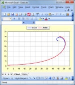
Images attached is a comparison between JMLC's spreadsheet (red) and my method (blue) with same condition.
Best regards,
Hsieh W M
Attachments

Hello WHG,
Images attached is a comparison between JMLC's spreadsheet (red) and my method (blue) with same condition.
Best regards,
Hsieh W M
How does it compare with that produced by DJM's Horn Loudspeaker Response Analysis Program [1]?
[1] http://www.hornresp.net/
Regards,
WHG
Last edited:
Hello WHG,
Images attached is a comparison between JMLC's spreadsheet (red) and my method (blue) with same condition.
Best regards,
Hsieh W M
Any examples of other sizes? I did not succeed with opening the .txt file in Scilab, so the spreadsheet is my only option right now.
How does it compare with that produced by DJM's Horn Loudspeaker Response Analysis Program [1]?
Hi Bill,
I haven't checked the code to see if the calculations are identical, but the results appear to be very close to those produced by the "exact method" documented in my Post #1139 and subsequent related messages. Hornresp has the option of exporting data using either the "exact method" or Jean-Michel's 2007 spreadsheet method. The Hornresp "exact method" is extremely accurate.
Kind regards,
David
Attachments
I did not succeed with opening the .txt file in Scilab, so the spreadsheet is my only option right now.
Why not just use the "exact method" in Hornresp?
.I use non-JMLC round horns now, and I would like to simulate these midrange horns: http://a397.idata.over-blog.com/300x293/6/15/98/16/3voies-2.jpg
Some say they would sound less forward but still go rather low.
Any way to simulate these in hornresp? If not, a link to an example on how to simulate JMLC roundhorns would be appreciated.
Great software, btw. Did wonders for my midbass horn.
Some say they would sound less forward but still go rather low.
Any way to simulate these in hornresp? If not, a link to an example on how to simulate JMLC roundhorns would be appreciated.
Great software, btw. Did wonders for my midbass horn.
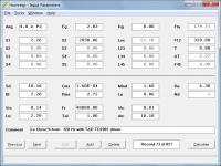
Hi Rewind,
No.
Example screenprint attached.
Kind regards,
David
Any way to simulate these in hornresp?
No.
If not, a link to an example on how to simulate JMLC roundhorns would be appreciated.
Example screenprint attached.
Kind regards,
David
Attachments
- Home
- Loudspeakers
- Multi-Way
- Jean Michel on LeCleac'h horns