For line driver / preamp duties, you can increase R7 to 1 k. The MOSFET heatsink is no longer needed, as the whole circuit now draws only 250 mW.
Thanks! I will try it on bread board first.
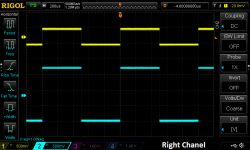
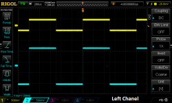
Normally you'd run 10 kHz and 100 Hz square waves to check for high and low frequency response, respectively. You are looking for a clean rise/fall with no overshoot. The 100 Hz response will not have a flat peak due to the AC output coupling - this is normal.
The square wave response is a diagnostic tool for troubleshooting a broken circuit or quickly checking that the circuit is working OK. Your square wave response just tells you what you already knew: your J-MoII is working fine.
Without a more sophisticated test and measurement setup, getting into a qualitative evaluation (of noise, distortion, frequency response and so forth) there isn't much more you can learn. I personally rely on simulations like LTSpice and my own ears for the operating point optimization vs. distortion, while using simple measurements to check against "unsimulatables/unhearables" like instability and noise coupling.
In addition to the square wave response (properly loaded), the FFT of the output (inputs shorted, no signal) is a quick and easy way to check your noise floor.
Not really, since there's a volume control between the input and the amplifier and anyway a square wave isn't representing any kind of standard input signal amplitude.
Adjust for 1 V peak output amplitude. And, if you want to be completist, check for 10 mV peak output amplitude also. This gives you the "large" and "small" signal response.
Adjust for 1 V peak output amplitude. And, if you want to be completist, check for 10 mV peak output amplitude also. This gives you the "large" and "small" signal response.
I completed the j-mo mkII preamplifier version on my breadboard. I used J310 as input, IRF610 as mosfet and a 10uf tantalum capacitor as output capacitor.
Because the current was lower now so I made the Sapphire PSU (lower part count) with 4700uf filter cap. I simmed and it does filter rip current about ~1mV with 30mA load. I plan to make the output voltage about 19V so I can set voltage at mosfet source ~ 7V to get a bit bigger voltage swing.
Now I need to do some listening test ...
In this context it would be p2p I guess, though think of it as the peak height.
I see. Thank you.
My crystal ball is out for repair again. Meanwhile you'll have to tell us what exactly you did. I have a hunch that loop gain in the preamp stage may be low, check device currents. Some details of the power supply may not hurt either, given the circuit's lowish PSRR.
Had some fun tweaking this one in sim. Don't forget including the customary ".option plotwinsize=0".
1. A CCS on the MOSFET is of far greater benefit than it may appear when driving near maximum current into 16 ohms. Repeat the exercise with 100 ohms at same output and watch distortion of the buffer stage essentially vanish when the CCS is employed. No surprise really, given that the same has been shown for the plain Szekeres long ago. Gains in the 16 ohm load case are small because 16||30.9 ohms isn't that much smaller than 16 ohms alone, i.e. a 30.9 ohm resistor makes a half-decent current source for a 16 ohm load as-is.
2. Replace the 330 ohm JFET collector load resistor with an equivalent current source (even if with 10k in parallel to even things out across the audio BW), and distortion is reduced considerably due to much increased loop gain. (The bipolar transistor also turns into a transimpedance amplifier then.) At 1 Vp out, we're talking <-80 dB 2nd, <-100 dB 3rd.
3. I tried bipolar input instead of the JFET while keeping device currents, but there seems to be little benefit doing so (maybe 2 or 3 dB less distortion, nothing major). With the standard feedback resistor values, lower JFET gm is of little consequence, and (nonlinear) input capacitance is much reduced by feedback as-is.
4. Replacing the buffer MOSFET with a BJT makes things a lot more sensitive to capacitive loading. I have to include several ohms of series resistance to make it stable with 10 nF, more than the output impedance of the MOSFET-based circuit. I had a hunch there'd be a good reason why most everyone builds a Szekeres with a MOSFET rather than a BJT...
(Admittedly a 100R series resistor in the base connection got the problem sorted while being less intrusive than the output series R, though at the expense of linearity. OK, we're going to stick with the MOSFET.)
Last edited:
Missing attachments?
The advantages of CCS are indeed at maximum at near clipping. The flip side of that argument is that at the power output where most people will actually listen it will make very little difference to the distortion, and only add noise. The main benefit, I feel, concerns PSRR.
Replacing the JFET with BJT would make matching easier, but the biasing network ends up more complicated and the input impedance suffers considerably.
Re 4. I'm surprised it makes such a difference given the output device has no feedback. I'll have to look into this. More info on what you did to get the sim to show this would be welcome.
I thought my schematic files would be too boring to post. It really was just one of those you posted at some time with stuff swapped out. I even stuck with boring ideal current sources, as I mainly wanted to see what was doable.
I didn't save the file with bipolar buffer, but I used the stock 2N3019 model for that. The MOSFET was entirely unimpressed with either 10 or 100 nF in parallel to 100 ohms, while the bipolar was not amused even at 10 nF. Which is a bit low for my tastes, given that a headphone cable can easily have 1 nF (that's the order of magnitude for common 3 m Sennheiser cables).
I'll have to look at what exactly makes the MOSFET less susceptible to oscillation here. I know that a common mechanism in case of bipolars is impedance transformation of base series inductance to something containing negative resistance by the first-order dropoff in beta (including 90° phase shift). MOSFET gm would be expected to be eventually dropping as well though? I'll have to read up on this, not at this time of night though (current daytime temperatures mean that windows are to be kept open, and you don't want to be attracting the entire population of midgets outside).
Attachments
Thanks. Plenty to think about.
Midges. Not midgets. Probably.
attracting the entire population of midgets outside
Midges. Not midgets. Probably.
- Status
- This old topic is closed. If you want to reopen this topic, contact a moderator using the "Report Post" button.
- Home
- Amplifiers
- Headphone Systems
- J-Mo Mk II headphone amplifier