It is very important info for me. So, if I use AKG K701 (impedance is 62 ohms) , then I'll might use Black Gate NX Series 680µF 35V instead of 1000uF Elna. Did I get you massage correctly?
Black Gate NX Series 680µF 35V, Sonic Craft
Black Gate NX Series 680µF 35V, Sonic Craft
Yes, that's right. In fact with 62 ohms you could use as low as 330 uF.
Capacitance values below that will reduce the bass response a little, but depending on how the response of the headphones is tuned this may actually improve the linearity or in any event result in more pleasant balance overall.
You are free to use whatever value for C1 you want, there is no impact on the circuit other than the bass response.
Hello Richard.
I've been using MK I of this amp for a few years now and absolutely love it. However, I got pretty interested in this new modification and would like to try it. The only thing I'd like to know is whether I could use less gain, because my GrubDAC has strong output and I almost never get past 12 o'clock and 50% volume in media player.
The question is then, which is the lowest gain I could go for? Is there any problem involved with stability or something? I really don't need anything past gain 1 or 1,5. My 55 Ohm AKGs are driven well.
BTW My parts in the original schematics are: 1uF Solen MKP fast cap on input, BF245B, IRF 510 with non-inductive Caddock 20 Ohm 35W resistor, 1000uF Elna Silmic II on output, running on 15V from IRF540 mosfet regulator.
The minimum gain depends on the gate-source cutoff voltage, Vgs(off), of the JFET, as [Vgsoff] X [gain] = ~9 V (the bias needed at the MOSFET gate).
The practical difference in the position of the volume control between unity gain of the JMo and 10 dB (the normal kit JMO2 configuration) of the JMo2 isn't really all that big, but if you were to substitute the JFET with something like the J111 you might be able to reduce it to 6 dB or thereabouts.
The practical difference in the position of the volume control between unity gain of the JMo and 10 dB (the normal kit JMO2 configuration) of the JMo2 isn't really all that big, but if you were to substitute the JFET with something like the J111 you might be able to reduce it to 6 dB or thereabouts.
My question is related to Capacitor Rack found on your project page.
I use 9.3V secondary toroid, 1N4002 and 150R 5W ceramic resistor.
I measure 9.4V AC out of trany, but at resistor I see 4.8V DC RMS. Why do I have such big drop? Or it is OK since I have only half/positive parabola cycles.
By calculation, I have 62.6 mA current, so no issue that trany has too much load. Everything is fine with AC when I remove diode and I have 9.2V AC on resistor.
Attachments
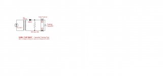
The output waveform isn't DC, it's more of a sawtooth pattern with 60 Hz repetition rate. The RMS value of that waveform is about 1/3 it's maximum amplitude of about 13 V - just under 4.8 V seems about right to me.
If you care to double check, remove the resistor and you should measure a DC value of about 13 V. (Without the bleed resistor, there is no dip of the voltage between diode conduction cycles and the output is essentially constant.)
If you care to double check, remove the resistor and you should measure a DC value of about 13 V. (Without the bleed resistor, there is no dip of the voltage between diode conduction cycles and the output is essentially constant.)
Yes, you are right.
I used 220uF 35V Ele cap and voltage is stabilized to 10.33V DC now. Thank you.
I prepared that jig for Black Gate NX 680uF 35V. Plan to bun them for about 300 hours prior installation into my J-Mo Mk II headphone amp. Some tech guy told me that they cook these for 550 hours. I'll see if I'll have that patient.
100h is sufficient to shake the worst out of them, they'll clear up further but you might as well be listening to them at that point.Yes, you are right.
I used 220uF 35V Ele cap and voltage is stabilized to 10.33V DC now. Thank you.
I prepared that jig for Black Gate NX 680uF 35V. Plan to bun them for about 300 hours prior installation into my J-Mo Mk II headphone amp. Some tech guy told me that they cook these for 550 hours. I'll see if I'll have that patient.
Managed to finish one channel as I don't have much time because of work. It works fine with BF245B, although 470 Ohm replacement for 1k5 doesn't work. I'd like to make second channel tomorrow. Looks like 9,5dB gain would work fine so I don't know why I was worried at first.
I noticed there is R0 20k log pot listed in BOM. However, I don't see it been drawn on schematics. Which min/max values do you recommend? And should I disconnect the 100k at gate?
Thanks.
I noticed there is R0 20k log pot listed in BOM. However, I don't see it been drawn on schematics. Which min/max values do you recommend? And should I disconnect the 100k at gate?
Thanks.
Well, it is absolutely amazing how these output BG caps improved my J-Mo Mk II headphone amplifier sound. Do not want to argue about technology and voodoo behind these 680uF 35V NX caps, but I trust my hearing memory and my sound change with more clarity and more details that I ever experienced with. I ran them about 160 hours by now and the change is obvious. Do not regret that I spent $89.75 + $1 for matching for each. For my case - it worth it....
Well, it is absolutely amazing how these output BG caps improved my J-Mo Mk II headphone amplifier sound. Do not want to argue about technology and voodoo behind these 680uF 35V NX caps, but I trust my hearing memory and my sound change with more clarity and more details that I ever experienced with. I ran them about 160 hours by now and the change is obvious. Do not regret that I spent $89.75 + $1 for matching for each. For my case - it worth it....
Indeed, those BG-N caps are really something special.
Hello!
I just want to start by declaring myself a newbie... Lol
I'm thinking of building this amp after coming across this thread from AudioPoutine who makes the cDAC+. I've always wanted to build the ODAC and O2 amp.
After reading through, I like all the positive comments regarding the amp and would like to order a cDAC+ and the amp kit in the near future. I have to admit that a lot of the technical details behind the power supply mods by the other folks go completely over my head, but I would like to make the most out of this build to get the best sound quality. What kind of advice can you guys provide?
I don't have any test equipment other than a meter. Not sure if anything else is required. I do have lots of wiring experience. Nothing in terms of actual electronic components. (Maybe just the basics)
My current setup consists of a borrowed Fiio E7 with an iPad and NAD Viso HP50 headphones. I would like to build the DAC/Amp combo in a single unit connected to a Linux box via USB of course and use the iPad merely as a remote control.
Thanks!
Don't worry too much about the power supply. All you need is 16~20 V DC, and you can swap it out for something different at any point.
You don't need anything more than a voltmeter to test the JMo2. AS I've said elsewhere, the circuit is pretty much bullet proof - all you need the voltmeter for is trimming the bias voltages.
You don't need anything more than a voltmeter to test the JMo2. AS I've said elsewhere, the circuit is pretty much bullet proof - all you need the voltmeter for is trimming the bias voltages.
Don't worry too much about the power supply. All you need is 16~20 V DC, and you can swap it out for something different at any point.
You don't need anything more than a voltmeter to test the JMo2. AS I've said elsewhere, the circuit is pretty much bullet proof - all you need the voltmeter for is trimming the bias voltages.
Nice!
I was thinking about it today, and that seems like the logical thing to do.
Thanks!
- Status
- This old topic is closed. If you want to reopen this topic, contact a moderator using the "Report Post" button.
- Home
- Amplifiers
- Headphone Systems
- J-Mo Mk II headphone amplifier