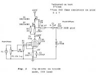
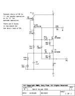
I have attached a schematic (courtesy of Damir) showing how to create a cascode CCS. The device shown is a DN2540, but the topology is equally applicable to the 10M45s.
You can create a low impedance mu-stage type output by taking the output from the top of the current set resistor R3 (as shown in the schematic) or take a conventional feed from the bottom of the resistor (tube plate).
pm
You can create a low impedance mu-stage type output by taking the output from the top of the current set resistor R3 (as shown in the schematic) or take a conventional feed from the bottom of the resistor (tube plate).
pm
Attachments
I worked thru Gary's graphs and got close to the same #s as his C pF chart. [I used the rightmost data points on the graph at 10000 Hz, calc: C = 1/(2 pi f Xc) ]
His graph is clearly not agreeing with Walt's graph. Part of the discrepancy may be due to the DC test voltage across the device. Walt's graphs are using something less than 18 Volts. What is Gary's DC test voltage?
Looking at the IRF820A data sheet, one can see the large effect of Vds DC voltage on capacitance:
at 1 V --> Coss = 490 pF
at 25 V --> Coss = 53 pF and Crss = 2.7 pF and Ciss = 340 pF
at 400 V --> Coss = 15 pF
Gary measures 4.426 pF
Looking at the DN2540 data sheet at 25V Vds:
Ciss = 200 pF (typical), 300pF max [Ciss is gate input cap., G to S and D, mainly to S]
Coss = 12 pF ("), 30 pF max [Coss is com. source outp cap., D to S]
Crss = 1 pF ("), 5 pF max [Crss is D to G cap., rev. transf.]
Gary measures 32.4 pF for the DN2540, Walt has 28 pF.
Comparing the DN2540 datasheet values with the IRF820 datasheet values shows about 1/2 as much of each parameter for the DN2540 versus IRF820, yet Gary measures 32.4 versus 4.426 in the opposite sense no less.
I would think that Coss or Coss + Crss would be the capacitance of interest for a single device, and this seems to be close to agreeing with the data sheet for the DN2540.
But Gary's measurement is way off from agreement for the IRF820a or IRF820b data sheet values.
IXYS does not give any cap. data to compare (and I emailed them once about this but got no reply). I did try to measure an IXCP10M45S with a Cap. meter once and got 80 pF at 30V Vds. But noise pickup was a problem for the meter, so I'm not certain about this.
Seems to me there is more discrepancy here between Gary's data and Walt's data than Vds alone can account for???
Don
Hmmm, another factor besides Vds that could affect the results is the operating current of the current sources. Walt's test of the IXCP and DN single devices was at 30mA. A lower operating current test would use a higher value of Rset in the source connection and this would raise the output Z just like a cathode resistor raises plate Z. (but I'm not so sure about output capacitance being affected this way?) We need to know the operating current and Vds for Gary's tests to compare with Walt's tests.
In any case, it is not hard to do the measurement again for the single IXCP. One just has to drive a signal (say 10KHZ cap coupled into the output and measure the signal showing up on a test resistor on the other side of the IXCP to ground. Using a larger test signal and a larger test resistor than Walt used should make this workable with just a good 50,000 count DVM.
Or use a 24 bit sound card to measure the test resistor signal and a resistive attenuator to measure the input signal (so as not to damage the sound card with the high input signal level)
Don
His graph is clearly not agreeing with Walt's graph
You ain't kidding !
This is all I could find on Gary's voltages/currents
The basic test setup is to set the sinewave generator to 10Hz, 100Hz, 1Khz or 10Khz. For most testing the sinewave generator output is set to 10 volts RMS. On the higher performance CCS's at 10Hz the output of the sinewave generator is raised to 30 volts RMS. to make the test signal visible.
Okay, this is approximately what I intend to do. My amp breadboard uses these as the tail determinant for the input/driver stage, and I can just take the balance of signals off the plates up into the MHz range, and see how it falls off; thus calculating the Z (and Xc).
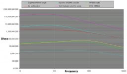
Funny thing, I'm still scratching my head over the graph of dynamic Z of the devices. Somebody tell me I'm missing some obvious thing here; Gary is showing the Zdyn of the IXYS chip at some tens of thousands of ohms, falling off (presumably due to the mentioned capacitance) for ALL of them from 10KHz on up or below. I have done some rough (as previously dissed) measurements, and I can tell you that the Zdyn at 1K is in the high hundreds of Kohms, and it's not falling off that soon.
What am I missing here?
Penitent Poinz
Gary is showing the Zdyn of the IXYS chip at some tens of thousands of ohms
Poinz, the second comma looks like a decimal place - it's actually 10megs.
pm
After thinking some about the DC operating current level having an effect on output capacitance, I'm now convinced that this would exist.
The higher the Rset value in the source connection, the more effect capacitive current feedthru has on the bias voltage level across Rset and hence the FET current output.
Its a little confusing, since a pos. increase in capacitive current feedthru increases the voltage drop on Rset, which then tends to turn the FET OFF! Countering the original AC increase.
I think one can look at it as a negative feedback loop, and higher Rset increases the open loop gain to AC current, which then decreases the final error. So doubling Rset to get half the DC current decreases net AC feedthru error by half.
So a current source's effective output capacitance should be proportional to it's DC current setting to first order. (my new theorem! )
This may be enough to explain the 55.6X discrepancy (for IXCP...) between Gary's and Walt's results. The Vds effect might acount for 3 or 4X if Gary used 100s of volts instead of 18V (actually more like 17V Vds after subtracting the Rset voltage out) And if Gary used 2 mA instead of 30 mA, this would give another 15X.
But if these corrections fix the IXCP disparity, they then ruin the near agreement on the DN... results . So something is still off somewhere! Arrrgh! On that note, I will now try to get some sleep.
Don
Let's see. Open loop gain should be something like Rset*gm so output capacitance should be something like Coss/(Rset*gm + 1)
If Output C = Coss/(Rset*gm + 1), one needs to take into acount of variation of gm with current and the variation of Coss with Vds.
Within a fair range of currents for Fets, gm is proportional to current. So for a depletion mode current source, lowering Rset to get more current also increases gm by the same amount. (unless the current is enough to reach the device's gm saturation level) Coss varies roughly as 1/Vds^.7 except below 20V Vds where it really takes off.
This makes the 15X correction to the IXCP results mentioned above disappear, since Rset*gm stays largely constant versus current.
Using Cout = Coss/(Rset*gm +1),
I put in the IRF820 data sheet parameters (gm adjusted for 2 mA and Coss adjusted for 100V Vds) and I get near Gary's C output result. However, using the DN2540 data sheet parameters (adjusted for Vds and current) I get more like 1 pF at 2 mA and 100V Vds. No data sheet parameters available for the IXCP... to try.
If this formula holds up, then one thing it points out is that it is better to use a 9V battery gate bias, instead of lowering Rset, to get higher DC current. This will then cause the output C to drop by roughly 10X.
So it would seem that IXCP... or DN... depletion mode devices need cascoding or 9V battery bias if one needs lower capacitance than default. Since one needs a battery to cascode in most cases anyway, one could skip using a depletion mode device altogether. Just use some lower Coss, and cheaper, Mosfets like FQP1N50, FQP1P50 with 9V battery bias or a 10V zener/pullup resistor reference (or LEDs).
The P-channel FQP1P50 allows one to use zener/LED bias off the B+ for a plate load CCS.
Don
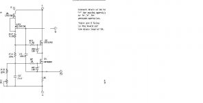
I myself took the liberty of making a prettier schem of the CCS section of Gary's circuit, for my own files. Looks worth a try, if I can find the device (Digi-Key seems not to have it).
Aloha,
Poinz
An externally hosted image should be here but it was not working when we last tested it.
Aloha,
Poinz
I myself took the liberty of making a prettier schem of the CCS section of Gary's circuit
The circuit I posted was drawn by Damir and downloaded from Audio Round Table. I don't think anyone can claim design rights as it is straight out of EE001.
Gary's CCS latest circuit is shown in this attachment. It outperforms the straight cascode using either the DN2540 or 10M45s.
Whether the added performance is worth the extra complexity is up to you.
pm
Attachments
Re: IXYS 10M45S (TO 220 package)
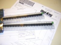
Well Digikey has the fastest delivery I ever witnessed, processing the order started Tuesday morning and the babies are already on my desk!!
And my thanks go to Tubelab for the tip
I still have some extra 10M45S. If anyone in EU is interested, pls drop me a pm.
markanica said:I have been wanting these babies for over a year now, so I went ahead and ordered 100 pcs.
Well Digikey has the fastest delivery I ever witnessed, processing the order started Tuesday morning and the babies are already on my desk!!
And my thanks go to Tubelab for the tip
I still have some extra 10M45S. If anyone in EU is interested, pls drop me a pm.
Attachments
Mach, I have been parsing stuff on the web for twelve years now, and that is the ugliest image I have ever seen, bar none!
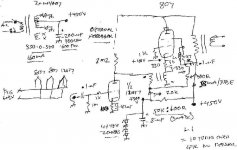
I'm not blaming you, mind, but does anybody have a parts list for this circuit, so I can pretty up the picture? I can see that the main(output) sand is the IRF820(B?), from the image name, and a few other parts values, but those FETs over on the left side of the image?
Late breaking news; I just went and looked in my files at that image, and it's not nearly as bad as it looked on the page here, but:
Why are what look like zeners called 'VR1' and 'VR3', and for a sand-iggnerunt Maui boy, what does the designation '1BV' tell me about them?
I still can't read the part dez for the two Q3 and Q4; is it 'LND150'?
Thank Yew, from the bottom of my very tiny brain,
Poinz
that is the ugliest image I have ever seen, bar none!
Having just opened it, I must agree it is pretty ornery !!! I had to do a greyscale to meet file size restrictions. Fortunately, Leadbelly's post shows the schema in all its pristine glory.
FETS are indeed LND150, and zeners are 18V.
However, my vote for the most aesthetically challenged image must go to this unparalleled masterpiece from down under.
Attachments
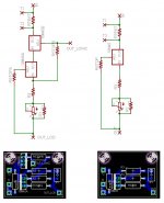
I am thinking about getting a few circuit boards for these IXYS chips made. I designed a basic version and a version using the cascode circuit -- the cascode board would become the basic version with a small jumper. The DN2540 appears to be pin compatible (as does the LM317 I think) so it could be used as well.
I also added a couple of small enhancements. These are a resistor (RTEST) and some test points such that one could measure the voltage drop to determine the current (or use the spots for an inline current meter). I also added a resistor in series with the trimmer so the ccs does not accidentally get run flat out. There is also a resistor in parallel with the trimmer in case of intermittent contact with the wiper during adjustment. All of these can be bypassed. Also, the trimmer is on the side so a panel mount trimmer can be used.
There is room for clip on heat sinks, but if you needed to dissipate 10W or something, some creativity would be in order.
The boards are about 3cm x 4cm
If it looks like people would be interested in these, I may go ahead with a small run. I am guessing that a pair would be on the order of $8 or so plus maybe $1 to ship -- and diyaudio needs to get their cut too.
-d
Attachments
- Status
- This old topic is closed. If you want to reopen this topic, contact a moderator using the "Report Post" button.
- Home
- Amplifiers
- Tubes / Valves
- Ixys IXCP10M45s IC