What are they opinions of Broskies IXCP + LT1085 HV regulated power supply? It is so simple but is the only reasonable power supply I have found with a low enough ripple to be appropriate for my application. The sound is a little too solid state-like in the bass department, but the background is dead black.
Is this ripple rejection acceptable to you? If yes, then you can try this one also. Its simple too. You can exchange its enhancement mode CCS with depletion mode Ixys or Supertex, and have even lower parts count. R1 scales the current by a 2.2V/R1 crude formula, the trimmer fixes needed Vout. Up to 300Vout with MJE350, more with -400V PNPs. 15-50V Vin-Vout difference is OK. Whatever current is not demanded by the load is constantly burned on the shunt NMOSFET. Allow +20% constant on top of your load's peak demand for that. Its reported as better than some series regs for tone and smoothness by enough builders.
Attachments
Is this ripple rejection acceptable to you? If yes, then you can try this one also. Its simple too. You can exchange its enhancement mode CCS with depletion mode Ixys or Supertex, and have even lower parts count. R1 scales the current by a 2.2V/R1 crude formula, the trimmer fixes needed Vout. Up to 300Vout with MJE350, more with -400V PNPs. 15-50V Vin-Vout difference is OK. Whatever current is not demanded by the load is constantly burned on the shunt NMOSFET. Allow +20% constant on top of your load's peak demand for that. Its reported as better than some series regs for tone and smoothness by enough builders.
Thanks I would need a higher voltage transformer, but will save this for when I build another.
Like this?Can the IXCP10M45's be run in parallel ? I have another project where I need 250 mA CCS.
Attachments
hi Guys,
I have used IXCP10M45S as plate loads with satisfactory results in the past. I have also built cascoded current sources using two IXCP chips (circuit diagram is a courtesy of the fellow DIYers and can be found elsewhere on this forum). These CS seem to operate properly, although I never done the extensive testing.
Recently i acquired a batch of IXCP10M45S from Mouser and decided to do couple of simple measurements:
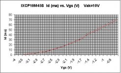
1. Id vs Vgs for fixed Vak=10V. This measurement is supposed to duplicate the chart in the data sheet.
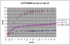
2. Id vs Vak at several fixed Vgs (characteristic curves).
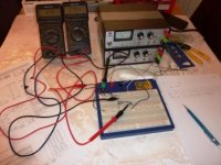
My experimental setup is shown in the attached photo. Really. there is nothing much in there, just the meters, regulated power supplies, paper and pencil (no computers or automatic data acquisition). Very much like good old times") . One power supply is providing Vak and there is an ammeter to measure the Id. Another power supply is for Vgk.
. One power supply is providing Vak and there is an ammeter to measure the Id. Another power supply is for Vgk.
1. I measured Id vs Vgs at Vak=10V. The result is shown on the attached chart.
2. I measured Id vs Vak at three fixed Vgs: -1.52, -2.2 and -2.58 V. The results are shown on the attached chart.
these results are obtained for ONE chip. however, I repeated the first experiment using another chip from the same batch and the results were the same.
I would estimate the experimental error conservatively around 5% which is also indicated with bars on data points.
Now the results:
1. Id vs Vgs differs significantly from that of provided by data sheet. For example, I measured Id=11ma at Vgs=-2.5, while data sheet chart shows 25ma. i guess this is not a big deal, because we adjust Id experimentally anyway.
2. Id vs. Vak (characteristic curves). I expected the saturation region to be much flatter if you consider Id=20ma curve, the slope (more precisely, the reciprocal) is around 6.5K, far cry from the stated 160kohm.
Also, the pinch off region is around 2-7V (depends on Id). This is important for the cascode operation (see below).
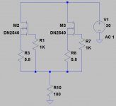
3. I tested a cascode current source consisting of two IXCP10M45S. The lower chip uses 120ohm current setting resistor connected between K (negative terminal) and ground. The gate of the lower chip is grounded. The K of the upper chip is connected directly to the A (positive terminal) of the lower chip. The gate of the upper chip is connected to the K of the lower chip ( sorry, but it was easier to describe the circuit here than to draw it)
I applied the voltage directly to the cascode and measured the current through it at two points: applied voltage Vb=17.8V and Vb=26.4V. both voltages are supposed to be in the compliance range of the cascoded current source. here are the results:
Vb (applied voltage, V) 26.4 17.8
Id (ma) 20.85 20.46
Vr (voltage on the resistor, V) 2.483 2.346
Vakl (voltage across the lower chip, V) 2.59 2.49
What I am concerned is that Vak for the lower chip (which supposed to source current) is VERY close to the pinch off region and thus operates on the border of the compliance range. i don't think this is the optimal condition to operate the chip.
Also from above data I calculated the equivalent resistance which is only 22Kohm .
I do appreciate your thoughts and comments. Also would love if somebody points out how to derive analytically the dynamic output resistance for this particular cascoded current source. I tried but failed so far.
Regards, irakli
I have used IXCP10M45S as plate loads with satisfactory results in the past. I have also built cascoded current sources using two IXCP chips (circuit diagram is a courtesy of the fellow DIYers and can be found elsewhere on this forum). These CS seem to operate properly, although I never done the extensive testing.
Recently i acquired a batch of IXCP10M45S from Mouser and decided to do couple of simple measurements:
1. Id vs Vgs for fixed Vak=10V. This measurement is supposed to duplicate the chart in the data sheet.
2. Id vs Vak at several fixed Vgs (characteristic curves).
My experimental setup is shown in the attached photo. Really. there is nothing much in there, just the meters, regulated power supplies, paper and pencil (no computers or automatic data acquisition). Very much like good old times
. One power supply is providing Vak and there is an ammeter to measure the Id. Another power supply is for Vgk.1. I measured Id vs Vgs at Vak=10V. The result is shown on the attached chart.
2. I measured Id vs Vak at three fixed Vgs: -1.52, -2.2 and -2.58 V. The results are shown on the attached chart.
these results are obtained for ONE chip. however, I repeated the first experiment using another chip from the same batch and the results were the same.
I would estimate the experimental error conservatively around 5% which is also indicated with bars on data points.
Now the results:
1. Id vs Vgs differs significantly from that of provided by data sheet. For example, I measured Id=11ma at Vgs=-2.5, while data sheet chart shows 25ma. i guess this is not a big deal, because we adjust Id experimentally anyway.
2. Id vs. Vak (characteristic curves). I expected the saturation region to be much flatter if you consider Id=20ma curve, the slope (more precisely, the reciprocal) is around 6.5K, far cry from the stated 160kohm.
Also, the pinch off region is around 2-7V (depends on Id). This is important for the cascode operation (see below).
3. I tested a cascode current source consisting of two IXCP10M45S. The lower chip uses 120ohm current setting resistor connected between K (negative terminal) and ground. The gate of the lower chip is grounded. The K of the upper chip is connected directly to the A (positive terminal) of the lower chip. The gate of the upper chip is connected to the K of the lower chip ( sorry, but it was easier to describe the circuit here than to draw it
)I applied the voltage directly to the cascode and measured the current through it at two points: applied voltage Vb=17.8V and Vb=26.4V. both voltages are supposed to be in the compliance range of the cascoded current source. here are the results:
Vb (applied voltage, V) 26.4 17.8
Id (ma) 20.85 20.46
Vr (voltage on the resistor, V) 2.483 2.346
Vakl (voltage across the lower chip, V) 2.59 2.49
What I am concerned is that Vak for the lower chip (which supposed to source current) is VERY close to the pinch off region and thus operates on the border of the compliance range. i don't think this is the optimal condition to operate the chip.
Also from above data I calculated the equivalent resistance which is only 22Kohm
.I do appreciate your thoughts and comments. Also would love if somebody points out how to derive analytically the dynamic output resistance for this particular cascoded current source. I tried but failed so far.
Regards, irakli
Attachments
Indeed. I have found, however, that one of my favorite ways to build a cheap and easy amp is to use one of these on the plate of the driver tube and bias it (the tube) via an LED. You can effectively drop tons of different tubes in as they will find their own operating point, so long as they are reasonably close and share the pinout, of course. I also tend to put in a switch to change heater pins (such as from 12at7 to 6dj8) which really opens up the possibilities. The additional resistor is one more factor to have to keep track of.
Here's the basic idea:
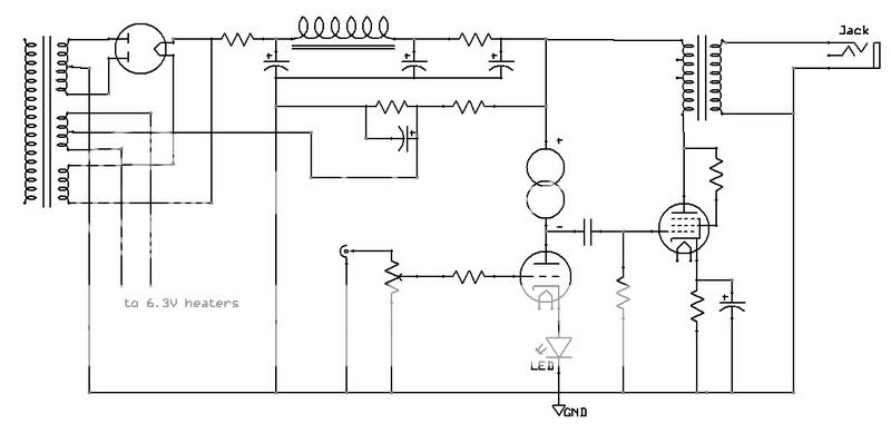
This one uses a 6w6 output tube, some edcor transformers. I've tried about a dozen different driver tubes in it -- everything from 5963, 12av7, 12at7, 6dj8, 6n6p, etc. The 5963 was actually one of the best sounding here.
I like this circuit very much!
What data should the LED have to work with 12AT7?
Have you tried DN2540 for CCS? What current are you running it at?
- Status
- This old topic is closed. If you want to reopen this topic, contact a moderator using the "Report Post" button.
- Home
- Amplifiers
- Tubes / Valves
- Ixys IXCP10M45s IC