Indeed. I have found, however, that one of my favorite ways to build a cheap and easy amp is to use one of these on the plate of the driver tube and bias it (the tube) via an LED. You can effectively drop tons of different tubes in as they will find their own operating point, so long as they are reasonably close and share the pinout, of course. I also tend to put in a switch to change heater pins (such as from 12at7 to 6dj8) which really opens up the possibilities. The additional resistor is one more factor to have to keep track of.
Here's the basic idea:
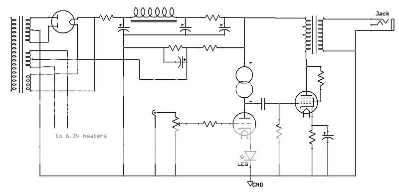
This one uses a 6w6 output tube, some edcor transformers. I've tried about a dozen different driver tubes in it -- everything from 5963, 12av7, 12at7, 6dj8, 6n6p, etc. The 5963 was actually one of the best sounding here.
Here's the basic idea:
This one uses a 6w6 output tube, some edcor transformers. I've tried about a dozen different driver tubes in it -- everything from 5963, 12av7, 12at7, 6dj8, 6n6p, etc. The 5963 was actually one of the best sounding here.
ErikdeBest said:Hi Dsavitsk
Could you make a sketch on how to bias the device with the 9V battery? And how long does the battery last?
many thanks
Erik
I think he uses the battery just to determine the correct resistor value for the desired current. Which is a lot safer then fiddling in a high voltage circuit....
Then, without the battery, insert the chip-resistor combo in the actual circuit
That is what I understand....
markanica said:
I think he uses the battery just to determine the correct resistor value for the desired current. Which is a lot safer then fiddling in a high voltage circuit....
Then, without the battery, insert the chip-resistor combo in the actual circuit
That is what I understand....
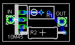
Yup. I actually made little circuit boards with spots for the chip, a stopper, and a trimmer for setting the current.
dsavitsk, that's a good way to do.
pftrdir, the drop across the CCS is what it needs to be. dsavitsk is using them as plate loads, so when the tube assumes its operating voltage, determined by the current and Vg-k, the remainder of the B+ will be the drop, anode to cathode, across the CCS. I'm using them as the tail current determinant for a singly-driven diff-amp pair, and the drop for me is whatever my negative supply is (right now 66 volts off a tiny Amveco toroid and supply) plus the cathode positive voltage with the grid grounded, about 2 volts. The control (grid-cathode) resistance is thus in the 'hood of 300R, so I use a 250 ohm resistor and a 100 ohm 10-turn pot, and adjust in. As dsavitsk can probably affirm, there is some example-to-example variance in them; the same control resistance on any pair of them will yield currents up to 10% or so different.
I'm still getting used to using these things; for some circuit calculations you sort of have to think backwards how it's going to go. I'd like to use these as a plate load as well, since I can get more voltage across the tube and thus more linear swing, but I wonder what happens, f'rinstance, if I have the tail CCS set to 8mA, and each plate CCS set to 3.8mA . . . ? For me, this is the sort of situation I would just have to put in the breadboard and see.
dsavitsk said:
Yup. I actually made little circuit boards with spots for the chip, a stopper, and a trimmer for setting the current.
any chance for a diagram? thank you
the ixys seems to be easiest to implement due to very low parts count.
but how is the performance VS something like the ones designed by g pimm?
ps. I know g pimm used to have comparisons on the site but I can't remember the results and the pages have been removed.
thank you.
but how is the performance VS something like the ones designed by g pimm?
ps. I know g pimm used to have comparisons on the site but I can't remember the results and the pages have been removed.
thank you.
jarthel said:any chance for a diagram? thank you
Hardly worth posting, but posted nonetheless.
I also noticed that diyhifisupply has something similar. http://www.diyhifisupply.com/diyhs_sockets.htm
jarthel said:the ixys seems to be easiest to implement due to very low parts count.
but how is the performance VS something like the ones designed by g pimm?
ps. I know g pimm used to have comparisons on the site but I can't remember the results and the pages have been removed.
I don't have a direct comparison, but I can tell you that the IXYS chip sounds very good. I think it is at least as good as the Bottlehead style CCS, and while Doc B refers to the IXYS chips as fuses, I think they are a lot less fussy to work with. If nothing else, they can take a higher voltage which is a plus as the turn on spikes in the schematic I posted above were high enough (because the output tube was not conducting enough to cause a voltage drop across the PS resistors) to keep toasting transistors.
Maybe someday I'll build an amp that uses a CCS and that is astoundingly good, and that the only thing I can think to improve is the CCS. In that case, I'll look to some other CCS designs, but for now, these are fun for tinkering.
Attachments
dsavitsk said:
Hardly worth posting, but posted nonetheless.
I can't see it. :|
Figure 12a of the Walt Jung article mentioned above has the circuit diagram for the IXCP10M45S.
From figure 12b, same article, one can figure out the output capacitance of the IXCP10M45S and DN2540 using the sloping section of the curves, which are dominated by the output capcitance.
IXCP10M45S --> 125 pF
DN2540 --> 28 pF
I used the data points at -90dB
This capacitance is pretty high except for maybe power tube use, so one should cascode these. Drops to 4 pf for both in Figure 13d at 16 mA using the LM317 to cascode.
I seem to recall G. Pimm's site finding 3pF for the IXCP10M45S, which would be in near agreement if for a cascoded circuit.
Some nice alternative cascode devices would be FQP1N50 and FQP1P50 Mosfets (enhancement mode N and P channel, 500 V, 40 W and 63W). These have 20 pF and 40 pF raw output capacitance alone.
Using a 9V battery to bias their gates up and referencing that to the top of the bias resistor for the other depletion device below, makes this capacitance largely disappear. (as done in the LM317 cascode, Fig. 13c, Rset/Out terminal, except there is no battery here since the top device is a depletion mode one too. Putting in a few Volts battery there would help for higher currents than 16 mA though.)
(The top device gate capacitance current is then funneled thru the bottom device Rset to re-program the bottom device to subtract the same current from its output.) Being Mosfets, depletion mode or enhancement mode, none will draw any DC current from the 9V battery.
Don
Use of any CCS in the tail of an LTP is less critical than in service as a plate load because the cathode impedance is lower, and CCS imperfections are less of a problem. Less - but not zero, however. Will it work? Sure, it will function. Would cascoding make it audibly better? That requires building and listening to know. Cascoding is pretty easy; so I'd do it just about anywhere a CCS is needed.
Poindexter said:how would one cascode an adjustable CCS? I know how to cascode tubes, BJTs, MOSFETs, simple devices; but this is a complex integrated circuit.
I would suggest you start by reading Walt Jung's excellent two-part article on CCSs in the recent AudioXpress issues. He shows several variants of cascoded CCSs. These are available on-line:
CCS part 1
CCS part 2
- Status
- This old topic is closed. If you want to reopen this topic, contact a moderator using the "Report Post" button.
- Home
- Amplifiers
- Tubes / Valves
- Ixys IXCP10M45s IC