Yeah. I know that feeling. It's certainly more fun reinventing the wheel with your mind then just copying it.
The answer to the circuit is certainly right under your nose if you look, but I like what you are doing here, something different is more interesting. I like the active current source you are using with the depletion mode mosfet.
Looks good so far. Keep going.
The answer to the circuit is certainly right under your nose if you look, but I like what you are doing here, something different is more interesting. I like the active current source you are using with the depletion mode mosfet.
Looks good so far. Keep going.
I have some ideas for a "J2MeToo" utilizing the Semisouth R085. The United Silicon Carbide jfet is similar, but with specs different in a few places - higher capacitance, for instance. It's a possible substitute for those who didn't grab the Semisouth part while it was available. The Infineon SiC jfets are also available at Mouser for a price. If I recall correctly, Semisouthfan said that these were lateral devices - I'll have to check back to make sure I'm not misquoting him. The difference is perhaps intriguing enough to get a few of the Infineon parts for messing around.
Anyway, the amp is sufficiently different that I'd feel better doing a simulation before I built it. I have a call out in the Semisouth boiler room thread for an R085 model, but if anyone here can point me to one, I'd appreciate it. It's also an excuse to unlimber the Orcad model editor and learn how to use it. If I get desperate, I might go ahead and use the model from USC.
Anyway, the amp is sufficiently different that I'd feel better doing a simulation before I built it. I have a call out in the Semisouth boiler room thread for an R085 model, but if anyone here can point me to one, I'd appreciate it. It's also an excuse to unlimber the Orcad model editor and learn how to use it. If I get desperate, I might go ahead and use the model from USC.
The Infineon part has a relatively huge input capacitance and a smallish junction-to-case thermal resistance. This means that the die is likely larger than the Semisouth jfet. This may also be due to using a different technology than the Semisouth or USC jfets. Of the 3 devices, the Semisouth part has the lowest capacitance, followed by the USC part, distantly trailed by the Infineon.
Choky, thanks for the model - I may have a chance to unpack it and give it a spin this weekend.
Choky, thanks for the model - I may have a chance to unpack it and give it a spin this weekend.
Here is a possible J2MeToo topo simulated as a preamp stage with immediately available PSpice device models. I used the J107 in the output stage, as I have a bunch of them and they are a high IDSS device, relatively speaking. In an actual power amp, I'll probably end up using Zetex p-channel mosfets in the input diff pair instead of 2SJ74 for the needed voltage rating (60V vs. 25V), as I'm using mirror rather than resistive loading. As you can see, the THD and harmonic distribution ain't bad for 2V output signal (20X gain).
Attachments
Here is a possible J2MeToo implementation using Darlington Vbe multipliers for extra bias. If I remember correctly, the R085 samples I have in hand required about 5V of reverse bias for a bias current of 1A. To get the 25W RMS claimed by the J2 spec, one would need about 1.25A bias current, assuming you can get 100% modulation of the upper JFET. The values so far are set up to approximate this condition.
I added a little extra voltage on the rails - more may be needed to attain the stated power, depending on the large signal characteristics of the amp near clipping.
I doubled the bias current in the input differential stage to improve gain and linearity. Unlike the J2, this amp is set up for unbalanced rather than balanced drive, since that's all I have in my home setup.
This circuit hasn't been simulated yet. I'll get arounf to it when I can take the time to figure out adding the R085 model to my PSpice library. complicated by the fact that it's tied up with Orcad Capture. Holler if you have comments or questions.
The J2MeToo gain cell simulated previously might be interesting to build using PN4391 jfets in the output stage, as they have higher voltage capability than the J107s I used.
Attachments
I may do the J2MeToo gain cells shown a couple of posts ago using the LSJ74s and LS4391 samples I won from Linear Systems in a design contest - more on that elsewhere when I finish up a paper I owe them that has been postponed by my main computer taking a massive Sh**. I'm still not completely up to speed with new hardware and software (but almost).
Based on the circuit in post #47, I did a gain cell that I might consider using in a phono preamp. With that in mind, the input differential stage was cascoded to reduce the Miller capacitance presented to a phono cartridge at the input - definitely a consideration for a MM cartridge. With the cascode, I had to add an extra RC network on the diff stage output to prevent full-tilt oscillation. The included pic shows the current schematic along with the output harmonics for a 0,001V, 10kHz input signal. Though the THD is low, the 5th and 7th harmonics stand out, quite different from the non-cascoded circuit shown in post 47. I fear listening problems from this preamp. Comments?
Attachments
One more observation - the use of the IXYS FET as current source (aleph-modulated or not) could be applied to a lot of the earlier Zen circuits with resulting simplification.
I've been thinking about such things lately. Is there a reason you went with the IXTH16N20D2 instead of one of the other IXYS depletion parts like the similar IXTH16N50D2? The IXTH16N50D2 in particular has the same transconductance and similar Ciss but half the Coss, but maybe this doesn't matter for a source follower? I am still working on how to convert datasheet numbers into conjectured audio performance. The IXTH6N50D2 and IXTH6N100D2 could also be nice.
Just curious.
Last edited:
The thread started out as uses for the 200V device, now that they have become available to mere mortals. Having said that, it looks like you could use the 200V device or the larger 500V device interchangably. I have both, and would save the 500V device for an app more in line with its voltage rating. I use the 0.8A/500V device all the time as a current source with more umph than the Supertex/Microchip DN2540 in many of my low voltage apps.
Sure, I am happy with those graphs and use them all the time to guess operating points before testing in the real world. The IXTH16N50D2 I mentioned is very similar to the IXTH16N20D2 in most of the data.
Study the shape of the curves. Is it strongly pentode in character at your operating coditions or does it have a large triode region?
What is the effect of temperature?
Many other things to look for depending on what you want.
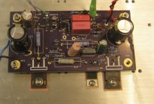
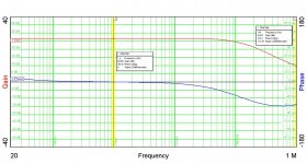
I'm building an amp using a fake SIT and an Ixys 200V topside modulated current source similar to the circuit in post #32. I'm calling it "Aleph Mc SIT", and hopefully it'll make a showing at BA16.
Here's a pic.
I ran up one channel this afternoon, and the amp draws about 1.6A of bias current - somewhat hot, but survivable I can tweak that down a bit. The output offset is ~20-odd mV - good enough for government work. I also ran a gain phase plot.
Here's a pic.
I ran up one channel this afternoon, and the amp draws about 1.6A of bias current - somewhat hot, but survivable I can tweak that down a bit. The output offset is ~20-odd mV - good enough for government work. I also ran a gain phase plot.
Attachments
Last edited:
After fixing a couple of bonehead mistakes, the other channel is now running, and it's time to think about how to box this amp up. I have toriods coming from Antek, and alumina washers from the Mouse. Both will be useful.I also have a couple of ideas for generating a floating bias supply for the topside depletion mode current source to get rid of the Darlington and enable bias adjust with a trim pot, but not for this go-round.
- Status
- This old topic is closed. If you want to reopen this topic, contact a moderator using the "Report Post" button.
- Home
- Amplifiers
- Pass Labs
- IXYS 200V Depletion Mode Mosfet Now Available