Here's what I've been playing with so far, with your usual ring of two current source standing in for what eventually will replaced by an Ixys depletion mode fet. I need to wrestle with the simulation some more to vanquish a low level HF oscillation that is superimposed on the entire output waveform when I do a hirez simulation. Don't know if it's local or global in origin - maybe a frequency response plot would be illuminating. Anyway, it's early days, and more work until I even think about breadboarding this thing.
Attachments
OK, with some minor revisions, the circuit (shown below) now simulates with no fungal fuzz on the output sine (translation - no parasitic oscillation), and distortion is around 0.015% at 8V peak output, 10kHz - mostly 2nd and 3rd. There is nothing stopping anyone from ditching the output capacitors and running this thing with a split supply, with the input referred to ground - that's what I'll do.
What appeared to tame the oscillation was reducing the feedback resistor values by a factor of 4, and making the gate resistors on the input mosfets match at 1k. Before, one was 1k and the other was 100 ohms, an oversight on my part.
The actual realization of this amp will use an IRF260 for the bottom output mosfet, and the current source will be replaced by a single IXYS depletion mode fet, making everything much more simple. I may do some tweaking to get the static balance a little tighter on the input stage. This should reduce the distortion a bit more.
Attachments
wrenchone,
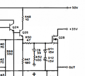
did you (could you) try bob cordell's approach of a fairly small series r at the gates with a r-c termination?
see excerpt from his 50w mosfet amp.
mlloyd1
did you (could you) try bob cordell's approach of a fairly small series r at the gates with a r-c termination?
see excerpt from his 50w mosfet amp.
mlloyd1
Attachments
Last edited:
oops , edit timed out on me.")
i also remembered bob actually commented on this approach somewhere.
i found it and wanted to share the link: http://www.diyaudio.com/forums/solid-state/136341-awesome-cordell-amp-4.html#post1723129
mlloyd1
i also remembered bob actually commented on this approach somewhere.
i found it and wanted to share the link: http://www.diyaudio.com/forums/solid-state/136341-awesome-cordell-amp-4.html#post1723129
mlloyd1
Here's a preliminary circuit for an amp making use of the IXYS 200V, 16A depletion mode device. It could just as well have used the 500V device that Nelson used in his "Delite" amp. The output stage consists of a buffered "Fake SIT" on the bottom using an IRFP260, and the IXYS device on top used as a Aleph-style modulated current source to set the output quiescent current (1A in this case). A split supply is used to eliminate output coupling caps. Close matching of the input mosfet pair will be required to minimize the DC offset at the output.
Another possibility would be to use a pair of the IXYS devices in a clone of the First Watt J1 amp. I'll leave that for (much) later, unless someone wants to chime in and propose a schematic - It'd be simple enough and probably require a small negative boost supply, just as in the case of this circuit.
Another possibility would be to use a pair of the IXYS devices in a clone of the First Watt J1 amp. I'll leave that for (much) later, unless someone wants to chime in and propose a schematic - It'd be simple enough and probably require a small negative boost supply, just as in the case of this circuit.
Attachments
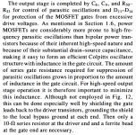
First off, it's the First Watt J2 I should be talking about here rather than the J1 (if such a beast even exists). The rationale for the J2 was exploiting the superior distortion characteristics of the Semisouth SiC jfets as compared to the usual workhorse IRFP240. The IXYS devices may (or may not) work as well in this respect as the Semisouth jfets. They will cerrtainly be easier to use in this topology than a conventional enhancement mode device. As a refresher, the skeletal view of the J2 topology is shown below. Obviously, "some assembly" will be required...
Attachments
One of the positive aspects of this project was finally understanding what Nelson was doing with his Aleph current source and getting it to work with simulation. The circuit I posted earlier will probably need some tweaking for optimum operation. Tweakables include the Aleph current sense resistor, and the voltage divider for the PCH/NCH buffered fake SIT. More on that as time allows.
To the guy who posted his preliminary preamp circuits here - leave a reference so we can go to a new thread and comment. I had some observations, but wanted to save them for a new, undiluted thread of its own.
To the guy who posted his preliminary preamp circuits here - leave a reference so we can go to a new thread and comment. I had some observations, but wanted to save them for a new, undiluted thread of its own.
If someone was bound and determined to try and clone the First Watt J2 with available parts, the SiC jfets available from United Silicon Carbide or Infineon might serve. It would be interesting to see if they have the reduced distortion exhibited by the Semisouth SiC jfets as compared to the IRFP240.
One of the issues I noticed in the preliminary schematic in post #27 is that the Ixys current source (Q6) requires a fairly large R5 value (2 ohms) to set the bias current at the proper value of 1A. This goes back to the initial measurements I made on the 200V IXYS fet in post #11.
The large value of R5 represents a lot of source degeneration, reducing the gain of the current source and perhaps increasing distortion. On the other hand, the large amount of degeneration probably will help to linearize Q6. An interesting experiment might be to add a low impedance voltage drop to replace some of R5, resulting in a current source with higher gain and ease of modulation. This was discussed back in post #13, using a power Darlington Vbe multiplier to supply the voltage drop.
With that in mind, I grabbed a TIP122 power Darlignton, nailed its base to the collector, and measured its Vce voltage drop at 1A (with a heat sink). It came out as 1.4V pretty much on the button. With this sort of voltage drop, a multiplier is really not needed. The schematic shown here shows a TIP122 Darlington with base connected to collector via a 1k resistor added in series with the source resistor (R27 in this case). This allows the value of source resistor to be correspondingly reduced. Whether this will result in any benefit remains to be seen.
Attachments
Last edited:
If someone was bound and determined to try and clone the First Watt J2 with available parts, the SiC jfets available from United Silicon Carbide or Infineon might serve. It would be interesting to see if they have the reduced distortion exhibited by the Semisouth SiC jfets as compared to the IRFP240.
Only potential problem is that the current SiC JFETs require significant negative bias (more than -7V) to reach normal current levels, so a direct clone may not be possible. Perhaps the Toshiba 2SK1530 would bias similarly to the Semisouth parts, but they are not JFETs...
One of the issues I noticed in the preliminary schematic in post #27 is that the Ixys current source (Q6) requires a fairly large R5 value (2 ohms) to set the bias current at the proper value of 1A. This goes back to the initial measurements I made on the 200V IXYS fet in post #11.
1)Have you checked others for lower Idss?
2)If you raise current to 1.5A, what does the source resistance drop to.
In simulation ixth20n50d gives much lower Idss. Possibly worth a shot.
Edit: I see the TIP122 pretty much takes care of this problem though.
Last edited:
If you raise the bias current, the dissipation goes up with it. You also have to raise the rail voltages if you want to make use of that extra current, so you raise dissipation even more, or blow extra power for nothing if you keep the original +/- 20V supply. I haven't looked at any of the other devices in my 200V Ixys stash yet, but I don't expect them to be radically different from the one I tested. In the design presented, I wanted to keep output device dissipation to a reasonable level (20-25W) so as to avoid beating myself up doing the thermal design or having to use multiple output devices. The design as shown will probably be good for about 15WRMS/channel, depending on how good the current source modulation is for the top side output.
If I remember correctly, Nelson's J2 was based on the Semisouth R085, a depletion mode device. The R085 requires a good amount of back bias for a reasonable value of bias current, but a small negative bias on the gate can help fix that. United Silicon Carbide makes a device that is a rough equivalent to the R085, and they are obtainable. I still have enough of the R085s that I could play around with a clone design (read an original design that does what I think Nelson's might do), but it's not one of my top priorities.
If I remember correctly, Nelson's J2 was based on the Semisouth R085, a depletion mode device. The R085 requires a good amount of back bias for a reasonable value of bias current, but a small negative bias on the gate can help fix that. United Silicon Carbide makes a device that is a rough equivalent to the R085, and they are obtainable. I still have enough of the R085s that I could play around with a clone design (read an original design that does what I think Nelson's might do), but it's not one of my top priorities.
Probably depends on how much AC current gain on the constant current source, you deem most audibly pleasing
1.5A could be seen as a benefit for more reactive type of speakers eg 3Ohm dips or 4Ohm speakers. I prefer to bias for a 6 Ohm load as compromise as most regular speakers aren't ruler flat and I have a 2.5Way that hits 4 ohms in the bass region.
In the J2 I don't think Nelson uses any active Current Source cause the power halves into 4Ohms (from memory) but maybe cloning is not your goal.
For some reason I thought Papa used an enhancement mode jfet. My memory is not so good though.
Last edited:
There's a picture of the device on the 6 Moon's review of the J2, and it's an R125. I don't know if this is one of the enhancement mode devices or the "baby" R085. Someone who has the old data sheets stashed and available can enlighten us.
Edit - I enlightened myself using Google, and the R125 is one of the enhancement mode devices. I don't have any - I only have the depletion mode R085s, which may or may not have the same mojo. If you search on the web for "First Watt J2", you can access a copy of the J2 manual, where Nelson lays out the rationale for the amp and names his device.
A "clone" using the R085s might still be interesting, esp as I have some Linear Systems LSK74s looking for a place to play. Don't hold your breath, though...
Last edited:
- Status
- This old topic is closed. If you want to reopen this topic, contact a moderator using the "Report Post" button.
- Home
- Amplifiers
- Pass Labs
- IXYS 200V Depletion Mode Mosfet Now Available