No! If you do that Hornresp will see it as 99% like a closed box, the harmonics of the pipe barely show on the response graph at all - the output of the single terminus is close to nothing on the graph - and remember I have to put the driver in the middle of the pipe... just one terminus in HR so the driver is 50% offset.
Here is the situation - I am very familiar with Hornresp and It's not going to work, yes if you know allot about this type of resonator you can imagine how the response will look like from those sims in Hornresp... that's not my case and as far as the rest of the people posting on this thread they have difficulties understanding the basics of the enclosure.
I will build a pipe for testing to make real world observations since I don't expect in the near future any simulations turning up at the way things look. Unfortunately I don't have an anechoic chamber, measuring equipment and the time/willingness to build/test it as it would be best - by comparing it to a known design - simple pipe 1/4 resonator of same volume.
I'm in the middle of trying to use ABEC3 (son of AKABAK) that can do arbitrary structures using BEM. It looks like it could easily do what you're asking and you can download and use it as a Demo. The learning curve is steep and its not user friendly. I need it for an Omni project that does not fit any established model simulator. Its my "aspiration".
The question has also been previously asked and speculated about at http://www.diyaudio.com/forums/multi-way/180438-what-happens-when-tl-open-both-ends.html
Your experiment is 1 pipe, 1 driver, and its highly symmetric. I'll add it to my learning test cases. Don't expect anything in less than a week (student driver") ). What I find interesting about your idea is the possibility of N-TL to reduce the harmonic issues of a single TL.
). What I find interesting about your idea is the possibility of N-TL to reduce the harmonic issues of a single TL.
ABEC3
The question has also been previously asked and speculated about at http://www.diyaudio.com/forums/multi-way/180438-what-happens-when-tl-open-both-ends.html
Your experiment is 1 pipe, 1 driver, and its highly symmetric. I'll add it to my learning test cases. Don't expect anything in less than a week (student driver
). What I find interesting about your idea is the possibility of N-TL to reduce the harmonic issues of a single TL.ABEC3
Last edited:
You can apply a simple symmetry boundary condition to know what happens with double open ended TL. This is same as classical flute of shakuhachi flute TL. Lowest fundamental mode is 1/2-lambda. Lowest note is basically 2xfrequency of closed one end TL. Basically needs to be 2x the length to reach same note. So you could fudge simulation with regular closed one end TL model but cut length by half. There will be finer effects of resonances etc if multiple drivers or driver offset etc. but fundamental and 1st and 2nd harmonic predictions will be close.
First test
This is ABEC (actually just the internal AKABAK engine is running).
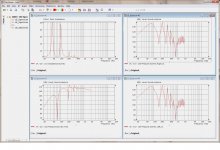
It's a square pipe with a driver (Alpair 7V3) mounted in the middle. So its a direct radiator with 2 equal (1m x 7cmx7cm) TLs off the back (right & left). Ignore the pressure level numbers, just use the shapes. There is very little internal damping just to highlight the resonances. I'm going to try different rear chamber next. Overall it still looks like a TL.
Still learning to drive, but I have checked the results for 2 Bass Reflex designs against HornResp so I've reasonable confidence.
This is ABEC (actually just the internal AKABAK engine is running).
It's a square pipe with a driver (Alpair 7V3) mounted in the middle. So its a direct radiator with 2 equal (1m x 7cmx7cm) TLs off the back (right & left). Ignore the pressure level numbers, just use the shapes. There is very little internal damping just to highlight the resonances. I'm going to try different rear chamber next. Overall it still looks like a TL.
Still learning to drive, but I have checked the results for 2 Bass Reflex designs against HornResp so I've reasonable confidence.
Attachments
Last edited:
Well ... I can appreciate the effort but that's a quarter wave resonator - look at the SPL graphs - the first resonance is at about 80 hz and the second at about 240 hz - make the calculations >>> that's the 3rd harmonic... you should have a resonance at 160 AND then another one at 240 if this would have been an open pipe.
Can you post an image with the architecture of the enclosure?
Can you post an image with the architecture of the enclosure?
As I said, "student driver" Stay tuned.
I agree, its suspicious. I tried to use the "enclosure" model so I think the rear chamber is modeled wrong. I'll create my own now. What I was expecting was to get an effect from independently varying the length of the two TLs but I don't see it. They are acting as one. Unfortunately this is not BEM yet, and the LE (AKABAK) engine is just a script, with no image.
Stay tuned.I agree, its suspicious. I tried to use the "enclosure" model so I think the rear chamber is modeled wrong. I'll create my own now. What I was expecting was to get an effect from independently varying the length of the two TLs but I don't see it. They are acting as one. Unfortunately this is not BEM yet, and the LE (AKABAK) engine is just a script, with no image.
Last edited:
Hi Don, seen this thread a couple of doors down? http://www.diyaudio.com/forums/soft...n-line-modelling-software-76.html#post5036760
Thanks, its interesting thread, and I have not seen it before. I like to see what designs and issues people are having with them. I do have a vested interest though, my Omni cabinet#4 bass design will be TL or MTL and I don't think it fits the mold either. I've never heard of that S/W (Transmission Line) . Most of these model simulators assume a conventional arrangement with known formulas to determine the performance. They all break when you try something novel, that's why I aspire to BEM.
home page for Leonard http://leonardaudio.co.uk/
home page for Leonard http://leonardaudio.co.uk/
Last edited:
If 2 is better, 5 must be fantastic http://www.diyaudio.com/forums/full-range/236779-panpipe-pentahorn-blh-speaker.html
More thinking outside the box.
More thinking outside the box.
Trial #2
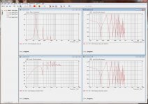
This is literally a driver connected to the middle of a pipe ( each side is 1m x 7cm x 7cm). It looks like its behaving as a 1/2 lambda resonator and the magic 16oHz is there. There is no "enclosure" in this model.
I'm still trying to figure out "observing" in ABEC as well as its radiator model.
Well ... I can appreciate the effort but that's a quarter wave resonator - look at the SPL graphs - the first resonance is at about 80 hz and the second at about 240 hz - make the calculations >>> that's the 3rd harmonic... you should have a resonance at 160 AND then another one at 240 if this would have been an open pipe.
Can you post an image with the architecture of the enclosure?
This is literally a driver connected to the middle of a pipe ( each side is 1m x 7cm x 7cm). It looks like its behaving as a 1/2 lambda resonator and the magic 16oHz is there. There is no "enclosure" in this model.
I'm still trying to figure out "observing" in ABEC as well as its radiator model.
Attachments
Last edited:
DIY means do it yourself
Well… as I said before for the average Joe it’s more simple to build it than to simulate it and that’s exactly what I did these last 2 days.
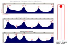
What have I built? A TL with both ends open and driver mounted at 50% of the length, folded at half point; length of the pipe is 2.3 meters, intended tuning frequency is 75 hz, for a 3 inch driver (not hi fi but with some excursion), internal volume of the enclosure is 10.8 liters. It’s made out of cardboard (just one piece) so it’s not rigid or perfect in any king of way.
What is the result? Some “measurements” – read: recordings of the terminus output (both together and each at a time) analyzed by SoundForge (spectrum analysis) to see what is what. So now I think we might know what is going on in the pipe.
Subjective impressions: It works! the answer to question in the title of the thread is Yes – it works it’s a fully functional enclosure, but it’s cardboard so it shakes all the way but doesn’t buzz at least since none of the panels is wider than 6.5 cm; so I don’t know how loud is the output (vs. to fully rigid version / vs. ¼ wavelength TL) but it’s there and you can hear it.
Conclusions: this is where the problems/confusion start – why is my 75hz open tube resonate at 55-60 hz ?!!! if this would have been one simple tube of the same size Honresp says it would have resonated at 70-72 hz… so it does not behave like a quarter wave resonator at all! Then there are the harmonics – the “missing harmonic” – the second is not present, it should have been at 105-110 hz but it’s not there, in fact neighter the third is there! We have 1st – 4th – 7th – 10th(maybe it’s the ninth just “late” by 30 hz) – what is that?! If you look at the open ends each is playing something different, but the second harmonic is not there! And that was the most important one because I was hoping to join forces with the first and lift the output under 100hz to get rid of the need for a horn… that would be the “promised harmonic’s” purpose. However there seems to be some extra output between the first harmonic and the third…. Don’t know how to interpret that. By the way the nulls resulted from interactions with the cone output will not be different so if you have extra output from the enclosure it’s a bonus.
I’m going so sleep on it and revise the situation – from enclosure to “measuring” to interpreting.
Well… as I said before for the average Joe it’s more simple to build it than to simulate it and that’s exactly what I did these last 2 days.
What have I built? A TL with both ends open and driver mounted at 50% of the length, folded at half point; length of the pipe is 2.3 meters, intended tuning frequency is 75 hz, for a 3 inch driver (not hi fi but with some excursion), internal volume of the enclosure is 10.8 liters. It’s made out of cardboard (just one piece) so it’s not rigid or perfect in any king of way.
What is the result? Some “measurements” – read: recordings of the terminus output (both together and each at a time) analyzed by SoundForge (spectrum analysis) to see what is what. So now I think we might know what is going on in the pipe.
Subjective impressions: It works! the answer to question in the title of the thread is Yes – it works it’s a fully functional enclosure, but it’s cardboard so it shakes all the way but doesn’t buzz at least since none of the panels is wider than 6.5 cm; so I don’t know how loud is the output (vs. to fully rigid version / vs. ¼ wavelength TL) but it’s there and you can hear it.
Conclusions: this is where the problems/confusion start – why is my 75hz open tube resonate at 55-60 hz ?!!! if this would have been one simple tube of the same size Honresp says it would have resonated at 70-72 hz… so it does not behave like a quarter wave resonator at all! Then there are the harmonics – the “missing harmonic” – the second is not present, it should have been at 105-110 hz but it’s not there, in fact neighter the third is there! We have 1st – 4th – 7th – 10th(maybe it’s the ninth just “late” by 30 hz) – what is that?! If you look at the open ends each is playing something different, but the second harmonic is not there! And that was the most important one because I was hoping to join forces with the first and lift the output under 100hz to get rid of the need for a horn… that would be the “promised harmonic’s” purpose. However there seems to be some extra output between the first harmonic and the third…. Don’t know how to interpret that. By the way the nulls resulted from interactions with the cone output will not be different so if you have extra output from the enclosure it’s a bonus.
I’m going so sleep on it and revise the situation – from enclosure to “measuring” to interpreting.
Attachments
The output from the ports is generally only useful <200Hz (maybe) because the avg power drops (despite narrow spikey waveforms). The TLs output is the combined response of all outputs, lower freq from the TL ports and mid+upper from the speaker.
The port peaks at [60, 140, 214] are consistent with sim [50, 180, 220] for a 1/2 lambda resonator.
Realistically the freq results between physical and sim are never going to match exactly but they will be close. The cabinet absorption and flexure will effect the measured results. The simulator assumes perfect reflection and infinite stiffness, unless you make allowances for it. Your design is cardboard, and even good cardboard will flex a lot over 1m. The speaker also affects the measurements.
Are you really asking "I have a cardboard TL with an undisclosed speaker, can anyone predict its performance?"
Update, driver offset
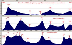
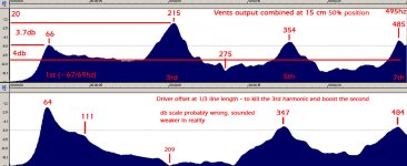
Update: I’ve been chewing on the matters discovered by building one of these open end pipes and as far as I can see simulations are thereabouts in nature and the fact that the numbers are not consistent (placement of harmonics) with theory is not that much of an issue; redrawing the conclusions from last time I posted – the pipe is resonating bellow the intended frequency (66 vs 72) and is playing only the odd harmonics just like a quarter wave resonator would have with half the waveguide length. As far as mysteries is concerned I still don’t know why the harmonics are where they are, the fact that one of the end of the pipe is playing something else than the other (one was playing even harmonics the other not!) and there may be some extra output from the pipe above the fundamental resonance, indicating that there may be some advantages compared to standard quarter wave pipe, the extra output is coming from the second harmonic for sure.
In the mean time I was busy trying to find out how to offset the driver in order to pump up the second harmonic to full power – well… as it turns out the way you offset the driver is by placing it in some special places where there are nodes or maximums of pressure/displacement; a maximum of displacement will be a minimum of pressure - http://www.feilding.net/sfuad/musi3012-01/images/lectures/pressure_displacement_modes.gif - and the way Hornresponse and one of the articles by MJ King points out the best way to offset a driver in a QW resonator is to place it at 20% or 33.3% from the closed end – there are the places where you have pressure nodes (or max displacement) for the 3rd and 5th harmonic which you kill if you place the driver there. The same turn out to be true for an open pipe (confirmed by offsetting the driver in real enclosure) – just place the driver at minimum pressure of a harmonic to kill it – which means that the 50% position of the driver is a position that kills the second harmonic, and the 4th… and also the 6th! So now I know why for sure why there was no even harmonics in position A (driver at 50% waveguide length).
The optimum position for offsetting a driver in an open pipe TL is at 66.6% (one third) line length because this kills the 3rd harmonic but leaves the second alive. Other possible positions would be at 60% line length (kills the 5th harmonic) but leaves the 2nd and 3rd alive and at 75% which would max the second harmonic but may weaken the fundamental. I don’t know anything about phase cancellation for now, but there will be nulls in the frequency response.
The subjective impressions of hearing the offset driver enclosure is that it sound weaker and it kicks weaker but not by much and there may be some losses due to the fact that the baffle in that area is weaker than before; it may actually be more hi-fi but with less SPL somewhere It does not make a good impression.
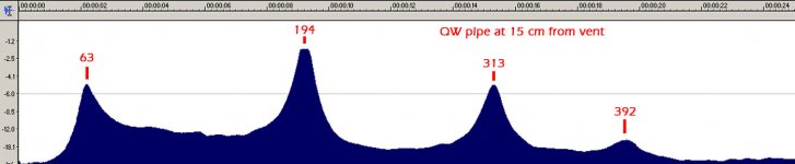
As far as the Holy Grail – the boost the second harmonic and therefore the output of the enclosure is half way done, in the sense that one of the open ends (the same as before) is playing the even harmonics and you can easily see that is really has constant max output from 50 to 150 hz!!! I don’t know any enclosure that can do that (some horns should do that I guess…). This output is somehow lost by phase or whatever… by the time you put the microphone at 15 cm from the pipe ends you have almost nothing left.
There are still unknown facts that may change things and get the TL that can fire on all cylinders (phase cancellation, driver offset, unknown strategies).
Update: I’ve been chewing on the matters discovered by building one of these open end pipes and as far as I can see simulations are thereabouts in nature and the fact that the numbers are not consistent (placement of harmonics) with theory is not that much of an issue; redrawing the conclusions from last time I posted – the pipe is resonating bellow the intended frequency (66 vs 72) and is playing only the odd harmonics just like a quarter wave resonator would have with half the waveguide length. As far as mysteries is concerned I still don’t know why the harmonics are where they are, the fact that one of the end of the pipe is playing something else than the other (one was playing even harmonics the other not!) and there may be some extra output from the pipe above the fundamental resonance, indicating that there may be some advantages compared to standard quarter wave pipe, the extra output is coming from the second harmonic for sure.
In the mean time I was busy trying to find out how to offset the driver in order to pump up the second harmonic to full power – well… as it turns out the way you offset the driver is by placing it in some special places where there are nodes or maximums of pressure/displacement; a maximum of displacement will be a minimum of pressure - http://www.feilding.net/sfuad/musi3012-01/images/lectures/pressure_displacement_modes.gif - and the way Hornresponse and one of the articles by MJ King points out the best way to offset a driver in a QW resonator is to place it at 20% or 33.3% from the closed end – there are the places where you have pressure nodes (or max displacement) for the 3rd and 5th harmonic which you kill if you place the driver there. The same turn out to be true for an open pipe (confirmed by offsetting the driver in real enclosure) – just place the driver at minimum pressure of a harmonic to kill it – which means that the 50% position of the driver is a position that kills the second harmonic, and the 4th… and also the 6th! So now I know why for sure why there was no even harmonics in position A (driver at 50% waveguide length).
The optimum position for offsetting a driver in an open pipe TL is at 66.6% (one third) line length because this kills the 3rd harmonic but leaves the second alive. Other possible positions would be at 60% line length (kills the 5th harmonic) but leaves the 2nd and 3rd alive and at 75% which would max the second harmonic but may weaken the fundamental. I don’t know anything about phase cancellation for now, but there will be nulls in the frequency response.
The subjective impressions of hearing the offset driver enclosure is that it sound weaker and it kicks weaker but not by much and there may be some losses due to the fact that the baffle in that area is weaker than before; it may actually be more hi-fi but with less SPL somewhere It does not make a good impression.
As far as the Holy Grail – the boost the second harmonic and therefore the output of the enclosure is half way done, in the sense that one of the open ends (the same as before) is playing the even harmonics and you can easily see that is really has constant max output from 50 to 150 hz!!! I don’t know any enclosure that can do that (some horns should do that I guess…). This output is somehow lost by phase or whatever… by the time you put the microphone at 15 cm from the pipe ends you have almost nothing left.
There are still unknown facts that may change things and get the TL that can fire on all cylinders (phase cancellation, driver offset, unknown strategies).
Attachments
More experimentation
As the experimentation got to a dead end I started wondering how would this enclosure (type) compare to a standard quarter wave TL (just one end opened) so I had to build one - the reason was to find out which one was louder because if the open pipe was weaker either meant that it needed more volume or that it wasn't as efficient... and we have other alternatives - a good TL and higher SPL enclosures (horn).
So I build one straight simple TL with same volume, same cardboard same intended tuning frequency and the results where very easy to hear - the quarter wave TL was louder and kicked harder, no measurements just by hearing it from the first few sound (piano... not "bass doom by thunderclaps"). I would also like to add that 2 of the 4 panels where much wider (2x) so there was more flex in each panel than with the opened pipe - more losses. Overall the SPL level was probably not much higher max 2 db but I have no doubt I would have chosen the standard TL because it sounded like it should.
This does not mean it's over for the open pipe design it just means it needs better investigation if there are ways to overcome what I have observed; for example I noticed after posting earlier that the second harmonic was canceling it self outside the enclosure because the openings where producing out of phase sounds... same thing for the 4th harmonic, allot of energy that is lost.
I will be thinking about the phase problem... suggestion are welcome.
There is another problem with this enclosure - because you have a very small section (half as that of a normal TL) the walls of the enclosure are closer to the driver and if it's really small - like mine - the waveguide was so small i could barely put my hand inside... I have to ask my self if air vibrates/behaves the same in such confined spaces.
Attachments
- Status
- This old topic is closed. If you want to reopen this topic, contact a moderator using the "Report Post" button.
- Home
- Loudspeakers
- Full Range
- Is there such a thing as a TL opened at both ends ?