update
Well it’s time for a new update:
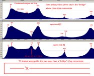
Main problem I have is how to “pull” the second harmonic out of the box and make it contribute to the output of the enclosure; the 2nd harmonic seams to be always out of phase between the pipe ends; I would like to point out that the enclosure must have driver offsetted from the 50% position because that one kills the second harmonic and all even ones therefore making it acoustically identical to a QW pipe (closed/TL). But there was a problem with offsetting the driver – the time necessary for the sound to travel from the driver to one end vs the other was different and that’s a recipe for out of phase problems.
So I came up with what I consider to be a solution – just make a “bridge” between the left and right sides of the “U” shaped folded pipe, resulting in a wave guide in the shape of the “A” letter – just look at the attachment. This is a frankensteinian TL for sure because it displays a weird thing – the 2.5 harmonic… I don’t know if it exists outside of this observation (subjective) but it’s weird and it even has a harmonic of it’s own (actually the 5th is normal); the driver sits at 20% folded pipe length; I still can’t make it sing the 2nd harmonic because outside it still plays only odd harmonics and maybe something of a larger SPL between 1st and 3rd but with this improvised method of “measuring” I can’t tell for sure; the only significant difference between this enclosure and a regular no offset TL (1/4) was that after adding stuffing the 3rd harmonic immediately disappeared leaving only a good solid platform above 1st harmonic, while the ¼ TL was almost unchanged from the same amount of stuffing.
As far as SPL is concerned they are very close, the “A” enclosure with stuffing definitely sound more hi fi in reality filling some of the empty spaces above 1st harmonic; the reason for which the ¼ TL sounded more aggressive it appears that it was related to that 3rd harmonic that added something all the time (a resonance) and made it louder.
I have other ideas of more frankensteinian open pipe TL but so far nothing seems to really work, no major improvements over the ¼ design. If anybody knows why the second harmonic does not poke it’s head out of the box please share.
Well it’s time for a new update:
Main problem I have is how to “pull” the second harmonic out of the box and make it contribute to the output of the enclosure; the 2nd harmonic seams to be always out of phase between the pipe ends; I would like to point out that the enclosure must have driver offsetted from the 50% position because that one kills the second harmonic and all even ones therefore making it acoustically identical to a QW pipe (closed/TL). But there was a problem with offsetting the driver – the time necessary for the sound to travel from the driver to one end vs the other was different and that’s a recipe for out of phase problems.
So I came up with what I consider to be a solution – just make a “bridge” between the left and right sides of the “U” shaped folded pipe, resulting in a wave guide in the shape of the “A” letter – just look at the attachment. This is a frankensteinian TL for sure because it displays a weird thing – the 2.5 harmonic… I don’t know if it exists outside of this observation (subjective) but it’s weird and it even has a harmonic of it’s own (actually the 5th is normal); the driver sits at 20% folded pipe length; I still can’t make it sing the 2nd harmonic because outside it still plays only odd harmonics and maybe something of a larger SPL between 1st and 3rd but with this improvised method of “measuring” I can’t tell for sure; the only significant difference between this enclosure and a regular no offset TL (1/4) was that after adding stuffing the 3rd harmonic immediately disappeared leaving only a good solid platform above 1st harmonic, while the ¼ TL was almost unchanged from the same amount of stuffing.
As far as SPL is concerned they are very close, the “A” enclosure with stuffing definitely sound more hi fi in reality filling some of the empty spaces above 1st harmonic; the reason for which the ¼ TL sounded more aggressive it appears that it was related to that 3rd harmonic that added something all the time (a resonance) and made it louder.
I have other ideas of more frankensteinian open pipe TL but so far nothing seems to really work, no major improvements over the ¼ design. If anybody knows why the second harmonic does not poke it’s head out of the box please share.
Attachments
I can see that there is quite an impressive amount of interest...
I have managed to find a simulation to clear things up - I was "protesting" that neither one of the simulations presented had the "missing" harmonic - the second... well there is one frankenstinian TL on the forum that does display such a response - http://www.diyaudio.com/forums/full-range/237384-flute-pipe-tl.html - unfortunately there is no drawing/scheme but according to the description - "a 224 cm long TL with 3.5 in x 2.5 in CSA, driven at the end witha Fostex FF85WK. The TL starts at the top, goes down and has single fold at the halfway point so that the terminus exits straight up" - with holes in it similar to a flute - "The resulting TL, if it were built would resemble a large flute-like pipe with oddly sized holes".
The simulation is not much but does prove that a TL can be tuned to 1/2 wavelength and play not just the odd harmonics but the even ones. The part that is missing (besides the "map") is a comparison to the same driver in an equivalent 1/4 WL / closed pipe / common TL - same volume and tuning frequency.
What I can tell you from my experience that putting many holes in a TL is not a good idea - this is not a flute that plays many notes, this is an enclosure that needs to have at least one resonance (1st harmonic) the rest may not be desirable and the cone plays the rest.
With regards the advantages of the "holy grail" (the second harmonic) boosting the output of the system above 1st harmonic that is not really in the simulation; what is instead is the null showing up after the second harmonic - probably curable.
As I said before there seems to be tons of interest...
I'm not making real progress just small steps, I'm still waiting for the big thing to turn up. There are other ideas and experiments that didn't make it in my previous posts - for example:
- changing the architecture from A shaped ho H (splitting the tip of A) doesn't change a thing, don't ask me why
- the last position I have not tried for the driver is at 75% but I'm beginning to believe it's the one that will kill the fundamental due to phase shift from longer side... I still need to make some king of way of to know the phase at the output of each ends
- mysterious behavior of pipe sides that don't show in any paper about resonating open tubes - this "can only be attributable to human error" - there is a slight difference in pipe section, both sides have the same problem, but I doubt it reaches 10% of total section and by the time you get to the and it's back to normal - begs the question just how sensitive is an open pipe to variations in tube section that 2 sides of equal length play differently just because of slight asymmetry?
- it even crossed my mind this cannot be made to work because the driver must stay in the middle of the pipe to avoid cancellation of main resonance
- I have some hopes that a carefully placed hole (let's call it "pipe end offset") in a normal TL but with double the length combined with a driver also carefully placed might make it play the right way - similar to the Flute TL I linked earlier; this also resembles the general architecture of the flute and organ pipe - not the first time it got mentioned that most holly of musical instruments
- another thing that crossed my mind is that the two ends don't like to be neighbors ... something to do with acoustic impedance but I have a vague understanding of the notion
- branching architectures might still have something left, but my hopes are much lower than before, mostly because you don't want to mess around with different arrival times / phase of the different sound sources
- one last mystery: what would a cone with both ends opened behave? this one would definitely play different things at each end - you can't even guess if it's contracting of expanding geometry!!!
Actually I was planning to make One Pipe to rule them All ! ... and the power could not be undone...
Some answers
Just found something looking for open pipes on google... slowly getting educated in the world of open pipes.
As it turns out people who build / enthusiasts of (church) organ pipes are very well educated in the field and know the acoustics of open pipes... I would say better than the TL in the world of acoustic enclosures - at least at the first glance. I found a discussion that was about open pipes that are folded 180 degrees - just like the one I have built - and as it turns out these things sound different than the same pipe as one long pipe, it appears that the second harmonic and all even ones cancel each other out for one strange reason - if you have 2 open end in proximity they like to settle in a different king of vibration in which the harmonic just goes out of phase at the ends - the air simply goes from one and to the other back and forth (imagine a piston slightly longer than a cylinder going in and out a little - when one end is out the other is in) - and this would explain why in my build the second harmonic - quote my self - "was not poking it's head out of the box". In other words a folded open pipe observed in the far field behaves like a normal TL... not 100% exactly.
I have also made a simulation in Hornresp for a compound horn turned in to a double TL separated by only the membrane (driver) resulting in 2 pipes operating with out of phase sound waves - the reason was to make observations with regards to changing of phase as the source of the sound is moved from the center of a long tube to the 1/4 point; result was that you get problems in the 100-200 hz area peaks and dips in freq. resp. Bellow I don't know but most likely on the safe side... still I don't like the idea of having two pipes with different delays; by the time I got to 1/4 position things where looking as if i was at the total cancellation point (I have to interpret the graph as if the two sides of the pipes had sound in phase initially). The 60/40% position seems to be the most likely to be ok for everything - this is the 1/5 offset driver equivalent from 1/4WL transmission line.
This type of enclosure appears in another thread - http://www.diyaudio.com/forums/subwoofers/246342-bose-bass-cannon-vs-tapped-horn.html
These observations are enough to call it a day when it comes to practical experimentation of the enclosure, I just don't have the means to compare different designs to make proper objective observations. The advantages will end up being small (in SPL).
The latest idea I have is to ditch the driver offset in favor of the conical shaped wave guide - why? - because if you have the driver at 50% position you get zero cancellation between the 2 ends due to delay-phase problem but you still have 2 pipes of different tuning frequency, in the sense that each output will have it's own output - in theory - thus resulting in extra output of the system. The purpose is to make the same volume of air of a normal TL "ring" at more than the usual first harmonic in order to produce extra output between 1rst and second harmonic.
By the way - the A/H shaped waveguides are not out of the game it's just that they need some space between the pipe ends and some luck.
The need for a software that can simulate this open pipe is as high as it gets to settle the thing... unfortunately ABEC is made for extraterestrial species and Akabak for fossils...
3 pipe monty
Hi there k: Over a couple of winters and culminating last year, I began listening to an experimental 3 pipe design driven by a single 10"Dayton DVC driver, (qts about 32hz). The driver sat on a ring allowing the rubber suspension to flex into a 3/4" deep cavity throat, the bottom of the cavity was another 3/4" plate manifold sealed into 3-four inch dia' heavy wall cardboard tubes. The three tubes are different lengths (about 42", 39", 36.5"). Each tube is terminated with 5 labyrinth plates which extend and somewhat restrict the bottom opening. No other stuffing was applied. The longest tube self supports on a base plate and the other tubes have a support attached to the base. The driver rear side (magnet side) is open to the air at the top. Listening indicated that deep bass notes were being reproduced and listening was enjoyable, however, one particular resonance was observable. I tried drilling small holes in the tubes, did not change the resonance, enlarged the holes several times to 3/8" dia, no help. Now having read your well written thread, herein, I realize that holes are not a viable solution. You have given me some hope that another solution may be possibly come to light and be tried next winter. I do not have calibrated test equipment, so no data available. Pictures were lost this week in a computer crash. ...regards, Michael
Hi there k: Over a couple of winters and culminating last year, I began listening to an experimental 3 pipe design driven by a single 10"Dayton DVC driver, (qts about 32hz). The driver sat on a ring allowing the rubber suspension to flex into a 3/4" deep cavity throat, the bottom of the cavity was another 3/4" plate manifold sealed into 3-four inch dia' heavy wall cardboard tubes. The three tubes are different lengths (about 42", 39", 36.5"). Each tube is terminated with 5 labyrinth plates which extend and somewhat restrict the bottom opening. No other stuffing was applied. The longest tube self supports on a base plate and the other tubes have a support attached to the base. The driver rear side (magnet side) is open to the air at the top. Listening indicated that deep bass notes were being reproduced and listening was enjoyable, however, one particular resonance was observable. I tried drilling small holes in the tubes, did not change the resonance, enlarged the holes several times to 3/8" dia, no help. Now having read your well written thread, herein, I realize that holes are not a viable solution. You have given me some hope that another solution may be possibly come to light and be tried next winter. I do not have calibrated test equipment, so no data available. Pictures were lost this week in a computer crash. ...regards, Michael
Last edited:
Thank you for interest and contribution but without a drawing or something to understand the architecture of the enclosure I think I'm lost - I don't know what you have built there.
Can you make a drawing similar to the ones I made to and put some of the measurements on the drawing (the tube length are the most important)?
The effects of the holes in the tube is that where you put them you will release pressure (air escapes outside) if that place turns out to be a high pressure area for a certain harmonic it cancels it out (or partial cancellation) and the general way things happen with musical instruments is that it moves the main harmonic to have the end at that point thus tuning the pipe to a higher frequency; how much of these rules are reflected in an enclosure is the part I don't know.
I will come back on the subject of your enclosure and the resonance you hear (I'll try my best) after you come back with the sketch.
Second harmonic demystified
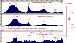
Second harmonic of an open pipe is different kind of a resonance because I have just confirmed that it is capable of "hiding" in the enclosure if the enclosure is folded; got the confirmation by placing the driver at 60% line length in the quarter wave control I have built (that had one end naturally opened and the other one had the circle hole for the driver as it was used in QW mode) - this enclosure is just one simple straight line with rectangular section. This time the second harmonic was very much present everywhere! There is something that doesn't add up to the theory - the fact that the enclosure is tuned to 117 hz it appears... when it suppose to be at 149 hz... don't ask why coz' I don't know (that mass loading?). Another observation is that the driver could not be left in the middle since that position kills the second harmonic; 5th was located above 500 hz that's why it's not in the graph.
This also gave me the idea that the open pipe enclosure could be simulated with a bass reflex cabinet with 2 ports as long as you have the freedom to move the ports independently to the ends of a very long shaped enclosure with the driver somewhere in the middle - suggestions are welcome to which software does this.
Attachments
Open pipe 2.0
This week I've been hungry for new ideas because there must be some way to make a waveguide the size of a TL to have wider output within and keep the pipe design. I mentioned above the idea of having a cone folded in 2 and opened at both ends in the hope that i get 2 different tuning frequencies - at 15-30 hz distace at first glance but can be optimized for sure to put them where you want them.
Haven't done that one yet but since I doubt it will be the absolute TL I continued to go down the road of the broadening of the frequency response of the pipe... and I started to mix different ideas derived from tube length gives tuning frequency / horn gives wide response, good impedance match / impedance mismatch is the source of pipe inefficiency at most frequency (the end plays but the outside environment reflects most of the sound back to make the standing wave)... and slowly I started fantasizing of a pipe that had the ability be simple (just straight 1/4 WL TL) but be willing to expand response in the vicinity of the tuning frequency ... the shape I was thinking about resembled the Karlson thing I was used to see on the forum but had no idea what it was (it was derived from a flute - each hole is for one tuning frequency - one at a time, idea is to convert multiple holes in to one that can play all notes with no restriction).
So i started to look what it was - well as it turns out it was something completely different than expected - the Karlson coupler suppose to be a replacement for horns but with added good dispersion... and it was designed around a closed pipe. After reading everything there was I started to have the feeling that either the people have forgotten another roman concrete recipe or there was a couple of maniacs making a big deal of an ancient "curtain"... because there was not much on the subject, even subjective impressions where not exactly abundant and if this was such a big deal as some of the claims suggest this was the big thing that audio enclosures lacked. Then I found out that nobody really thought about building a pipe with a wide(est) freq. output using the coupler... you know... a 50 hz TL with a Karlson coupler; there was a certain rigidity in the designs I saw... scaling up a drawing from the 50s is not what you call a (distinct) design...
Since I don't really know what to call this thing (snake oil from the past or ignorance from everybody) I'm going to have to build one - a TL with a coupler - none of that front loading thing interests me, I want to see the pipe go full gas / pumping on all cylinders; some of the effects described will be going on but the enclosure may not be as people might think judging by the way these things are built (image search all over the internet), this enclosure will have to be bigger and longer and with a smaller or even different (shaped) slot to work as I imagine it - as a subwoofer output, maybe a bandwidth of 50-80 hz located bellow 150, depending on the tuning frequency, but the output should be prime quality.
Will get back on this...
Just a quick update: I've been playing around with the Karlson slot thing and so far the needle points to "no improvement" - what is different is the fact that the wider (slot) and closer I got to the original exponential shape of the slot the more it seem to allow the passage of the rest of the audio spectrum and there was even an unclear source of the sound - not in continuation of the pipe but rather perpendicular to the slot (this was a rectangular pipe with a slot at the open end, the closed end had the driver, no folds); as far as low output is concerned there was no improvement... maybe there was some loss but no SPL gain from a the pipe.
From what I can see from the internet info there is no theory behind the Karlson slot/enclosure type/acoustics, no formulas etc. which can only mean that there is (only) a slight chance to make it work in the bass frequencies... as far as the rest of the audio spectrum I believe it works because I had some results. I'm curious how a pipe would work like the one you see in the drawings - cylindrical + 2/3 length of "curtain" shape... in the lower than 200 hz department. Hard to believe though that the audio world is ignoring a perfectly functioning enclosure that works better than a horn.
I'm still waiting for my memory to remember where is the Karlson cylinder present in nature (I know I saw it somewhere) and if it had acoustical role or not.
- Status
- This old topic is closed. If you want to reopen this topic, contact a moderator using the "Report Post" button.
- Home
- Loudspeakers
- Full Range
- Is there such a thing as a TL opened at both ends ?