I am curious about this claim "If using DC on a directly heated tube filament, a constant current source tends to sound better than constant voltage."
Is it because the filament/cathode is (AC) isolated from the filament power supply? I read that people claim AC powered DHT sounds better than DC powered DHT. Is it because of the same reason? Then, this opens some possibilities about wiring. Say, to reduce hum, One may use a pot between the two AC leads and the center tap, but not ground the center tap. Or, one can use DC to power the filament, but do not ground the DC supplier. Interesting claim.
vax9000
AC heaters apply 50Hz (or 60Hz) plus about 5% distortion to the heaters. The problem with DC heaters is that rectification produces a spray of harmonics, starting with the second, and the trick is to stop that getting everywhere. I've seen a lot of very poor DC schemes - at the very least you need to follow the reservoir capacitor with a regulator. Another issue is that not only does the rectification noise go forward (to the heaters), it goes backwards, into the transformer and is coupled elsewhere, and bigger reservoir capacitors make it more of an issue.
Another issue is that not only does the rectification noise go forward (to the heaters), it goes backwards, into the transformer and is coupled elsewhere, and bigger reservoir capacitors make it more of an issue.
That's precisely why Schottky diodes should be used in DC filament supplies. Stop the "hash" before it starts.
Constant voltage is needed. But if a voltage regulator starts increasingh a voltage slowly, it prolonges life of tubes. One way to bring it up slowly is to set up a current limit just above a normal working current, so while filaments are cold the current will be limited, but when they are hot the voltage is limited.
We are talking about some small picofarads between the filament and cathode. dV/dt, which 6 VAC has little of, is the noise source.
In the end, you either hear hum or you don't. I do agree that generating less diode hash in the first place is wise.
As far as Schottkys are concerned, yes, the waveforms look better. But the sharper corners imply spectral energy at higher frequencies. At the very freq's where all components begin to look like mongrels instead of R's, C's, and L's. Now jelly bean silicon diodes produce downright ugly waveforms, but, the spectral energy is distributed ats lower freq's... where normal components can "catch" them.
Not to counter Eli's advice by any means. Has any one here taken a look at the spectral output of different diodes? I would think that "soft recovery" might fair the best... after all, that is why they are built.

My preference is to bias the heaters some nominal voltage above the max cathode swing and leave them AC. The techniques would work with DC or constant current too I suppose.
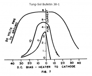
poobah, suprisingly according to Tung-Sol bulletin 38-1 from 1938 the primary leakage mechanism between heater and cathode, at least at those frequencies, isn't capacitive.
We are talking about some small picofarads between the filament and cathode. dV/dt, which 6 VAC has little of, is the noise source.
poobah, suprisingly according to Tung-Sol bulletin 38-1 from 1938 the primary leakage mechanism between heater and cathode, at least at those frequencies, isn't capacitive.
"Early in 1936, a Tung-Sol electrical engineer found that the heater cathode leakage current is essentially a thermionic emission phenomenon and that the flow of current is due to the emission of negative charges (electrons) and positive charges (positive ions) from the insulation coating on the heater to the cathode sleeve. The capacitance between heater and cathode, being of the order of 10uuF, is too small to constitute a leakage path."
According to Tung-Sol both positive and negative biasing work, with the former being slightly more effective. I don't quite understand how having the heater negative to the cathode works and the paper is also vague on what '20 volts RMS to ground' means. Cathode signal?
Yes, from cathode to heater though, drawing negative charges away from the signal terminal. Incidentally, a couple graphs show the relationship between heater voltage and hum. Dropping it to 90% rated knocks 15 dB from the induced hum.
"... wouldn't that encourage leakage?"
Yes, from cathode to heater though, drawing negative charges away from the signal terminal. Incidentally, a couple graphs show the relationship between heater voltage and hum. Dropping it to 90% rated knocks 15 dB from the induced hum.
Attachments
Hmmm, I gotta ponder this one. If Tung-Sol says so; I guess I want to believe it.
It sure seems that keeping the heater negative to the cathode, like we do the grid, would minimize the leakage.
I do notice that in some tubes, the spec's suggest you are allowed to take the heater much more negative than positive with respect to the cathode... I presumed breakdowns and leakages the cause for all this. Clearly, I am missing something here. I hate charts without matching schem's... like the cable thread.
They are both hot, catodes and filaments, and both emit electrons. It means, no matter how to bias, but bias such a way so filament powering AC is not rectified and don't produce harmonics. Capacitance is really small for 60 Hz, but may be enough for harmonics.
Also, symmetrical power with low Z to the ground helps.
But I personally prefer regulated DC.
Also, symmetrical power with low Z to the ground helps.
But I personally prefer regulated DC.
rdf said:So it's a rectification phemonenon! Out of curiousity, do you offset bias your DC filamanents?
somewhere in 12B4 thread (which one of many?
) I wrote that this is 'cause diode -like transfer characteristic between heater to cathode -talking about not-DH toobz.when you elevate heater supply potential on some (for start) 30 V above or bellow cathode potential ,transfer curve is pretty flat and pretty horizontal,so then you have minimal superposition (or-in other words-smallest amplification) of hum between cathode and heater....
and-what's on cathode-that's also on output

- Status
- This old topic is closed. If you want to reopen this topic, contact a moderator using the "Report Post" button.
- Home
- Amplifiers
- Tubes / Valves
- Is constant filament current better way to build amps?