Mr Evil said:I prefer polyester, since polypropylene capacitors tend to be physically very large in those sizes, as well as expensive.
Of course MKT Polyester is good.
But I find they are not that much cheaper than MKP.
So I go for Polypropylene MKP when looking for input capaciotrs.
The -3dB point "corner" frequency is the point when the magnitude of the capacitor's reactance matches the resistance.
f = 1/(2*pi*R*C)
where R is the resistance in ohms and C is the capacitance in Farads (note that 1uF is 0.000001). In the ideal case of a low impedance source the value R is equal to the input impedance of whatever follows the capacitor.
f = 1/(2*pi*R*C)
where R is the resistance in ohms and C is the capacitance in Farads (note that 1uF is 0.000001). In the ideal case of a low impedance source the value R is equal to the input impedance of whatever follows the capacitor.

This case is different that simple RC lowpass or highpass filters but the equation still works.
First, not considering the capacitors the voltage gain is equal to
( (R57||R53)/R8 + 1 )
where the "||" indicates "in parallel with".
The addition of C22 means that the total impedance of R8 and C22 in series will increase as the frequency decreases. At the frequency where the capacitor's reactance equals the value of R8, the value in the denominator of the equation above is sqrt(2) times larger.
This is approximately equal to the corner frequency (-3dB)... not exactly because of the +1 term because this is a non-inverting configuration, but close enough.
Along the same lines, the frequency where C73 is equal to the combination of R57 and R53 in parallel will cause another corner frequency. This will be a lowpass because as frequency increases C73 will cause the value in the numerator of the gain equation to reduce.
The equation in previous posts will also work for the highpass at the input formed by C3 and R58.
All of these highpass and lowpass poles are 1st order but they combine with each other. So if set C3 and C22 to the same corner frequency you will have a total of -6dB there and the -3dB point is higher than you initially inteded.
A good value to remember is that by one octave away from the corner frequency the response is still -1dB. So for example if you had 3 high-pass poles in a circuit at 10Hz, you'd get an actual -3dB point of 20Hz.
Sorry for rambling on.
If you had a single pole filter on it's own, the F-3dB can be predicted and you know that for a passive filter preceded with a near zero source impedance and near infinity load impedance that the Q of the filter will be 0.7 (1/sqrt(2))
If you cascade two passives filter the Q becomes Q1*Q2 ~0.5 if both filter are at the same frequency and meet the input and output impedance rules.
If you cascade three filters then the Q becomes ~0.35.
This is a very wide and slow roll off that extends many octaves away from the individual roll off points. Yes, it'll have F-3dB at the F/2 or 2*F frequency but the -0.1db point will be decades away. The phase shift extends even further.
If the NFB filter sets the pass band of the amplifier then that means that the input filter is passing some low frequency content that will generate a voltage across the NFB cap. This is not good. Ideally you never want any measurable AC voltage across the NFB cap. This is achieved by ensuring that the amplifier passband is determined by the input filter. This is the reasoning behind the scaling of the input and NFB filters, that has been repeated ad infinitum in this thread and others.
The -3dB point "corner" frequency is the point when the magnitude of the capacitor's reactance matches the resistance.
f = 1/(2*pi*R*C)
where R is the resistance in ohms and C is the capacitance in Farads (note that 1uF is 0.000001). In the ideal case of a low impedance source the value R is equal to the input impedance of whatever follows the capacitor.
Let's assume I have defined a 47kOhm imput impedance for my amplifier and I want a corner frequency of 100khz, which would be the capacitance of the cap for a highpass filter of 1st order?
input capacitance of a power amp must generally be high,
depending on the input impedance.
this cap s value must be adjusted to settle the 1/f
corner frequency of the amp, so it can be as much as 100uf.
it s not the normal purposeof an amp s input capacitance to act
as a high pass filter ,this role is better left to the preamplifier..
depending on the input impedance.
this cap s value must be adjusted to settle the 1/f
corner frequency of the amp, so it can be as much as 100uf.
it s not the normal purposeof an amp s input capacitance to act
as a high pass filter ,this role is better left to the preamplifier..
F=1/(2*pi*C*R)Let's assume I have defined a 47kOhm imput impedance for my amplifier and I want a corner frequency of 100khz, which would be the capacitance of the cap for a highpass filter of 1st order?
C=1/(2*pi*R*F)=0.16/(R*F)
But why you wont corner frequency so high.
it s not the normal purposeof an amp s input capacitance to act
as a high pass filter ,this role is better left to the preamplifier..
I know, but I dont use a pre
") So consider it an integrated (i.e. a power amp with stepped attenuator on the input)
So consider it an integrated (i.e. a power amp with stepped attenuator on the input)A better option would be to filter the output of the source, but i'm not sure if that can be done.
the input impedance is usually an input resistance.Let's assume I have defined a 47kOhm imput impedance for my amplifier and I want a corner frequency of 100khz, which would be the capacitance of the cap for a highpass filter of 1st order?
This resistor together with the DC blocking capacitor form a high pass filter, not a low pass filter.
This high pass filter is usually set somewhere between 1Hz and 10Hz, but some builders prefer it to be outside that range.
If you want a low pass filter, you require the source resistance and a capacitor to ground.
This is usually set between 100kHz and 300kHz. It attenuates RF and prevents ultra fast transients upsetting the input stage.
You will usually find resistor of ~1k0 combined with ~470pF at the input to make your low pass filter.
Let's take these two values and add the corrections required for the source impedance of the source equipment and the parasitic capacitances of the receiver. Rs source is specified as 500ohms.
The total R of the RC filter is 1k0 + 500r = 1k5.
The power amp has 10pF of parasitic and device capacitance.
The total capacitance seen by the 1k5 is 470p + 10p = 480pF.
The F-3dB = 1/2/Pi/R/C= 221kHz.
the F-1dB ~ 100kHz.
Member
Joined 2009
Paid Member
For lowest distortion when using electrolytic capacitors on the input it seems, from what I've read, that you want to minimize the a.c. voltage across them. For the input you want to pick a value 10x larger than would be suggested by a low frequency cut-off consideration. So instead of 1uF, use 10uF. The feedback bypass capacitor in a Lin topology amplifier has very little a.c. across it so a smaller value is just fine.
In my experience the type of coupling capacitor is not as significant as its size. I have found some designs to sound much better when I replaced a small polyprop or polyester (say 0.47 or 1uF) with a 10 or 22uF bipolar electro.
This tallies with theory in that it moves the filter time constant well below the lowest audio frequencies, meaning there is very little signal voltage across the capacitor and any distortion it adds is negligible. It also means the impedance of the cap is lower at lower frequencies, helping to reduce noise.
I was initially surprised to find this, having previously read that the type and brand of cap used is critically important to SQ and believed it. But in the end my ears were in agreement with theory and I think that's a good outcome
I'd stick with bipolars if you can fit them on the board, as they were shown by Cyril Bateman in his excellent series on capacitor distortion to have considerably lower distortion under all test conditions to polarised electros. Also if there is a large DC offset present on the output of the source device attached to the amp due to a fault, a suitably rated bipolar will handle this whereas a polarised electro might explode if the voltage is the wrong polarity.
If I think correctly, when the impedance of capacitor is equal to the resistor, that's the -3dB point on Voltage graph, not for Power graph. When you half the voltage, the power becomes quarter. The loudness will drop 6dB!
What's more, you can not guarantee there is only one high pass filter in the whole signal pass. Sometimes the 2 or 3 capacitor on signal chain, and you must count the capacitor on the negative feed back network too!
In that case, I suggest using 2Hz to calculate the value of capacitor instead of using 20Hz.
No.If I think correctly, when the impedance of capacitor is equal to the resistor, that's the -3dB point on Voltage graph, not for Power graph. When you half the voltage, the power becomes quarter. The loudness will drop 6dB! ..........
When the impedance of the capacitor (or inductor) is the same value as the corresponding resistor in the filter, then the two equal Voltages are 90 degrees different phase. When these are added you get the sqrt(2) in the addition. This results in -3dB at the turn over point and a net phase change of 45degrees for a single pole filter.
It is also the same filter frequency that is predicted by the model F(-3dB) = 1 / 2 / Pi / R / C for a single pole filter (this applies to both high pass and low pass).
It is -3dB on both power and voltage graphs. -3dB means half power, and 70.7% voltage. This is because the definition of decibel always relates to power, even when you are calculating with voltage.jxdking said:If I think correctly, when the impedance of capacitor is equal to the resistor, that's the -3dB point on Voltage graph, not for Power graph. When you half the voltage, the power becomes quarter. The loudness will drop 6dB!
The main point with coupling caps is to ensure that the one which sets the LF rolloff should be early in the circuit and of suitable dielectric. Others should set a lower frequency but you may be able to be less fussy about dielectric, unless a lot of gain is used. With little signal voltage across it, a cap can't distort.
Unless you have remarkable speakers, special ears and a very large room there seems little point in the main rolloff being much below 20Hz. I suspect that equality of rolloff between the two stereo channels is more important than the actual value, because our ears are sensitive to phase differences at low frequencies but much less sensitive to phase as a whole. If you like reggae or organ pedal music (and have speakers to match) then maybe 10Hz rolloff might be useful - but then you might start hearing arm-cartridge resonance from a turntable. Make the other LF rolloffs at 1-2Hz.
No.
When the impedance of the capacitor (or inductor) is the same value as the corresponding resistor in the filter, then the two equal Voltages are 90 degrees different phase. When these are added you get the sqrt(2) in the addition. This results in -3dB at the turn over point and a net phase change of 45degrees for a single pole filter.
It is also the same filter frequency that is predicted by the model F(-3dB) = 1 / 2 / Pi / R / C for a single pole filter (this applies to both high pass and low pass).
Thanks for reminding me. I missed the phase shifting thing in the calculation.
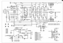
Hi guys,
according to the schematic below, I want to add a nice Alps 50K pot at the input of the LM49830 as a master volume.
May you suggest me what you think would be the best value/type of input capacitor, and where would be better to install it? (right at the rca input?)
Thanks in advance.
according to the schematic below, I want to add a nice Alps 50K pot at the input of the LM49830 as a master volume.
May you suggest me what you think would be the best value/type of input capacitor, and where would be better to install it? (right at the rca input?)
Thanks in advance.
Attachments
- Status
- This old topic is closed. If you want to reopen this topic, contact a moderator using the "Report Post" button.
- Home
- Amplifiers
- Solid State
- Input capacitor