Attention guys!....Michael Bittner, our MikeB, is working hard, going througth the
night...and asked me to publish Symassym4 and 5 schematic...and all details.
I will do it, openning new thread next wednesday.... as this thread here, this one you are reading, is going to die naturally, as questions already made, and doubts are near to finish.
Symassym is very good too.
In my mind; AKSA, also GEM, also JLH designs, Also Symassym, in different order than wrote above, are very good amplifiers...all them very good...each one with their own proper characterístics... wich one is the best.
Exist others good?
- off course exist many that i never heard, never assemble..but those i can sign under, as they are "State of the Art", each one one precious stone.
Those i constructed them, i tested them, i heard them for long time, i tried to turn better and i failled, they were compared and considered wonderfull..others assembled were nice, reasonable, supportable, tollerable and damn awfull and received a shot.
Of course, many of those failed as a result of my ignorance and incompetence...no doubts..but those four i wrote could beat my ignorance and low competence..they worked, beeing resistant to foolishes, to polarity inversions and produce cristal clear sound.
You Judge!.... all those guys are close friends..i cannot put them to figth...a dog's figth!
I have the pleasure to present you, some antecipation of Symassym...class AB.... 50 watts RMS also and using same voltage as GEM and AKSA...here is the diagram, without values..next week...wait for it please.
Mr. Graham Maynard made the kindness to simulate and compare with GEM, he said specifications was better to GEM...i do not know the percentual difference, and the details...he did not assemble...the ones that assemble was the designer, Michael Bittner, Mr. John Mateus, and I only.
Hugh Dean made his evaluation and told that he apreciated the schematic, and also apreciate the GEM schematic...he is a Lord.
regards,
Carlos
Attachments
Thanks Carlos
Thanks for the pictures they will be a lot of help. What about the GEM's stability with an ESL load? Anything to consider there? I ask though I do not have very much experience with electronics construction. There are lots of amps that will drive an ESL but not a lot that sound good with that load. Regards Moray James.
Thanks for the pictures they will be a lot of help. What about the GEM's stability with an ESL load? Anything to consider there? I ask though I do not have very much experience with electronics construction. There are lots of amps that will drive an ESL but not a lot that sound good with that load. Regards Moray James.
I have not technical conditions to say yes or no
But a Graham's sentence i can remember.
"One amplifier designed to ESL will be different of another designed to dinamic speakers"
Not only this makes a lot of sense, but seems to me, that he is avoiding his responsabilities for the Boooom!..plaft, póc! that may happen. (he is laughing now)
My feeling, just a feeling.... ESL will explode the amplifier output... ESL, as i could have some informations, are enormous problem to match, despite wonderfull sound...one step advanced related the ridiculous air pumps, that we have been using for more than a century, the speakers...air pumps...yeah!
I had informs, that usually the load is too much low in impedance,or have a transformer producing counter forces to audio signal , and this may create high voltage spikes...those spikes beeing bigger in voltage that the maximum transistor output VCE, made it burn.... maybe some zenner to hold those peaks...i do not know.
In your place.... will not try...but John Mateus, used the last JLH updated schematic, not only updated, also upgraded in components too... a Symetrical JLH last model.... 98 model...or 89 model...cannot remember exactly...and he use a ESL coupled in this class A amplifier without any problem.
Find Jmateus in our forum...and mail to him, he will be glad to talk about that subject.
Let's listen Graham...he may agree...or not...let's listen to him.
regards,
Carlos
stoker
"Douglas Self is the designer of the Blameless amplifier, blameless because it has very low distortion depite being classB. Don't ask DestroyerX how it sounds, he may kill himeslf."
i dont understand how is it possible to have a low distortion
from a class-b since there's no bias, how did he do it
can you provide a link of the schematic of this amplifier
in the meantime ill try googling to see if i can find anything
thanks for your help
cheers
mastertech said:I don't understand how is it possible to have a low distortion
from a class-B since there's no bias. How did he do it?
Can you provide a link of the schematic of this amplifier
in the meantime I'll try googling to see if I can find anything.
Thanks for your help.
Buy the book "Audio Power Amplifier Design Handbook" 3rd addition available through Silicon Chip magazine for $89. 10% off if you already subscribe. I'm surprised you haven't heard of Douglas Self and don't buy Silicion Chip.

http://www.dself.dsl.pipex.com/ampins/ampins.htm
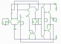
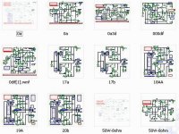
Re: Greg, here is the sketch, Graham will check for us.
Carlos, thanks for the sketch. I have looked through my books and stolen a few ideas.") Anyway, here's my sketch. The values are just ones I picked up as the most common, I don't know if these values apply in this case. I need to know the current flowing through the VAS bootstrap resistor but it is just too simple for me to work out.
Anyway, here's my sketch. The values are just ones I picked up as the most common, I don't know if these values apply in this case. I need to know the current flowing through the VAS bootstrap resistor but it is just too simple for me to work out.
destroyer X said:If some error, Graham will correct for us.
It is missed in the sketch, but the Q5 lower resistor, the 470 ohms, is in the reality one trimpot.
Carlos, thanks for the sketch. I have looked through my books and stolen a few ideas.
Anyway, here's my sketch. The values are just ones I picked up as the most common, I don't know if these values apply in this case. I need to know the current flowing through the VAS bootstrap resistor but it is just too simple for me to work out. Attachments
Hi Graham and Carlos,
I've been having a look at a layout for the GEM. I like to have all the components mounted on the PCB (excluding PSU). The output transistors are mounted on the PCB with the heatsink ledge between the transistor body and PCB. Like Rod Elliott does in some of his projects. (e.g. option 2 for the P3A)
I am wondering where you guys are mounting your 10,000uF filter caps (50V are big). Are they really on or near the amp PCB or am I misunderstanding and these are actually the PSU filter caps?
Could these be mounted on the PSU PCB and smaller decoupling caps used on the amp PCB. I suppose I'm asking if having large filter caps close to the output transistors are an important part of this design.
Thanks
I am using small electrolitc condensers directly over the amplifier board.
My PSU is inside a metal case, and many parallelled caps are inside.
In the reality Greg, there are two transformers, each one with their own full wave rectifier, and if i remember (do not know exactly) there are around 15000uF capacitance each rail.
I am using 40 centimeters of very heavy gauge wire from PSU to circuit, so, keeping wire resistance as small as possible..but always some tenths of ohms exist there... and this can create a charge-discharge cicle in the amplifier board... the oscilation will start because of that, when having too much wire resistance... one of the possible causes to start oscilation.
This was my first important information (my case Greg) when i was 9 years old...having any resistor to reduce voltage, in any amount, have to install condenser after to avoid oscilations.
Was very important to me, that experience in real world construction.
I think Graham, and the ones that can see schematics alike a color movie picture inside their brains, that will never accept an amplifier without a very close condenser...directly installed over the main amplifier board, and having very small distance from the board rail voltages.
Not only Graham, but also Michael will not accept small condenser over the board, as i use to do, and half world use to do.
Well, those guys, alike some hawk, have other "vision" and use to put those "Aircraft Carriers", those enormous electrolitics over the board.
Despite that i do not bother about appearance...in my point of view this is too much uggly in appearance...and i use to not do this way....but this may be result of my ignorance related this need.
I think you have the rigth to install your Condensers directly over the board, as suggested by Graham.
I will try without them over the board, but really i will be a little afraid, that i can be loosing something without install them over the amplifier board.
Let's see, if someone will run to help me to "kill" this doubt.
I am sorry, as i am kidding related the Blameless, but i remember very well that i was very deceptive.
After construction and adjustment, voltages perfect, good transistors, all them hi speed devices... Vbes more than perfect, off set very small, current balanced and Simulator results perfect.
When i switch the unit on...and the music used is the one i always use to start my testings (one from Dire Straits)..when reproduction started to play i said to my "Self"...THIIIISSSS is the Blameless!!!, and i started to walk in turns saying the worst words i learned in many languages, very, very, angry with that circuit.... really have low distortion...low noise...but have not something that i think was lost... audio quality, and maybe, this is connected to the presence of some distortions as i suspect.
Having AKSA 55 distortion chart, you will see that distortion are not incredible small, as 0.05 % or less, but sounds great!
Also the JLH have enormous distortion, and all the guys that constructed apreciate it's sound.
Exception is GEM and Symassym...those, having low distortion sound great too, when i could see that many brand names, showing very small numbers, also had some music without quality..something alike food without salt!
Maybe the distortion type, the measurement method, or something alike are producing those differences in numbers
Thank you Greg, i will use your schematic, and i am sorry, the one i suggest was "with inverted logics"....was wrong, i am very sorry.
The 100 ohms trimpot, that you substitute with a 47 ohms trimpot, with a resistor in series, i think 50 ohms will complete the standard value, and can be installed in the place you put interrogation marks.
The clever resistor network you made, for the bias adjustment, will be better to have a result of 1K ohms when you add all resistors together....but will work also, as normally this network is calculated from 3 to 10 times the real base current..so, will work great!, and protected against mistakes that can produce enormous current.... depending on supply capacity...the 220 will be the main protector.
I use 35 volts condensers to 35 volts rails, but industries never do this way, always bigger voltage ratios are used....normally 50 or 70 volts condensers to 35 volts rails.....i think will be more safe, and more expensive, more big and more ugly too...unfortunatelly. Decoupling 100N caps are very safe, to help drains starting oscilations to ground... electrolitics are coiled inside, as you know, showing resistances to high frequencies travell inside them going to ground.
Greg, if you know how to make, having a good CAD tool to help you, please, make this board you are telling that will prefer to use..this one with power transistors installed over it...and publish that board here, will be a very good cooperation.
I know my boards are ugly and strange... i first created them when very young and doing the same now a days...my board was created in 1970...this was made to be simple, fast and to go checking while assembling...to use glue to fix boards, to avoid shorts...but it is not the kind of work people prefer, as the guys majority in this forum, are producing diy work but alike professional does...not as home made diy work, without more pretentions are beeing done here...so...having the chance to help us...please, go ahead and prepare a more professional board, that will be very well received by the community majority.
regards,
Carlos
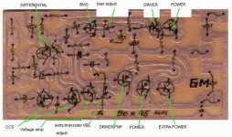
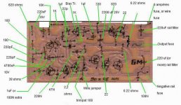
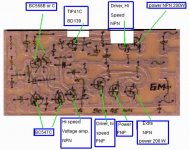
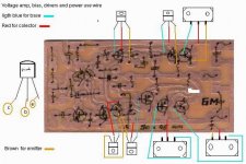
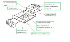
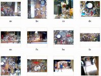
A new GEM board already assembled
Here is some distant images...not to see defects.
Twisted wires produce capacitance, have to keep them small in length.
Better than run 3 wires to each transistor, produce interconnections between them, from transistor emitter to colector.... joining colector using the heatsink conductivity and avoiding twist them.
Monday i will put it to run.
regards, and good weekend to all.
Carlos
Attachments
Hi Moray James,
Been busy ! I don't have access to electrostatics.
The weakness of a JLH class-A is its strength ! It is incapable of exceeding its pure class-A bias set output current, therefore it cannot even try to put so much current into a capacitive load that it oscillates.
I tried putting capacitors across the output of my 100W JLH at full output and I almost burned my fingers holding a physically small one that heated so quickly I had to drop it whilst the amplifier continued playing loudly into a loudspeaker.
So I have just tried the same with my GEM.
2uF crossover capacitor directly across output terminals - oscillation and spark.
2uF across loudspeaker terminals with 2m spkr cable - plays on just the same;
ie. there is enough inductance in 2m of spkr cable to prevent instability.
My view is that either a series 0.22 ohm resistor or not less than 2m of speaker would be okay, but then most electrostatics also have series transformer inductance/resistance that should protect from oscillation anyway. There certainly won't be any drive current related problems.
Hi Carlos,
Simulations suggested that my amplifier produced less distortion than Symasym at all levels, esp lower listening levels and 3rd harmonic, but my main reason for taking the GEM route is the way that this circuit deals almost resistively with back-EMF.
Except for the JLH class-A, I have yet to find another 'non full class-A' NFB amplifier that simulates similarly.
Yes Carlos you had me laughing again, not quite 'boom'ing with laughter though.
Hi Greg,
Regarding your bias sketch.
I use a clear bodied 15 turn 1k and 50R Bournes Multi-turn cermet trimmers. The adjustment is very extended for the class-AB adjustment but a little more critical though still easy for the class-A biasing.
I have not used those little horseshoe shaped horrors for bias adjustment for some time, and thus it did not occur to me that I should mention anything.
Just use 15 (or 10) turn pots as they are; it much more simple.
I don't like mounting power transistors on a pcb and then bolting them to a heatsink.
After a working lifetime of bad words related to thoughtless designers who turn simple repairs into ten times the work stripping everything down, well, what more can I say; there's clever/smart and there's common sense ! Swopping wires or trying a completely different device type when the are heatsink mounted is just so easy.
I use Panasonic 10mF/63V and these are not too big for PCB mounting, but again I want an easy construction, so for me they are either side of pcb.
A fuse and wires from psu can have a resistance, and I don't want to risk more common mode distortion than necessary at any frequency. That is my reason for a big 'C' after the fuse. The psu with smoother capacitors is separate. For all I know this arrangement actually helps the amplifier to sound good, I have not check other ways.
Nor did I instruct Carlos on how to build his. I e-mailed him the circuit and the next I knew this thread arrived. His capacitor placings are similar to mine and he mounts power transistors on heatsinks; maybe the same thought processes, or practical, or just old fashioned.
Cheers .......... Graham.
I would be glad to show you a Graham's picture, but he is humble and shy...
I think he will not apreciate that publicity about him.
So...sorry not to show..he is handsome, had kind appearance and a very good smile.
Has "daddy expression"....hehe...big daddy.
regards,
Carlos
I think he will not apreciate that publicity about him.
So...sorry not to show..he is handsome, had kind appearance and a very good smile.
Has "daddy expression"....hehe...big daddy.
regards,
Carlos
Graham Maynard said:Hi X.G.
Didn't get the chance to post this yesterday.
Thanks for your feedback, I'd love to see the circuit - can you show a copy ?
I have seen class-AB + CCS before, and I have seen claims that it maintains class-A operation.
To me all it does is maintain class-A in one half and offset the zero current class-AB crossover for the other, though such an arrangement can work better when the load is a *resistor*.
Here I have a separately active class-A device helping error correction at all times, and particularly during class-AB crossover at whatever voltage the loudspeaker might induce a class-AB current crossover. The lower class-A device is constantly working with the upper output half in the same manner that a JLH class-A amplifier operates.
I also retain JLH class-A bandwidth and low output inductance.
Cheers ....... Graham.
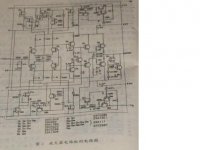
Hi,Graham
you are right.the Janpanese Power amp what I say just is Class AB output + CCS,like the OPA set in 'class A ' by many DIYer....but to me,it is the first amp using this method.
I can't find the original article now.this is the same circuit in Chinese magazine:
cheers
X.G.
Attachments
Hi Carlos,
You mention me fitting some electrolytics on the board.
I have indeed, and up to 1mF for the rails.
This time I am fitting only the parallelling capacitors, with the 10mF beside the pcb and them held in place with double sided sponge tape.
And I agree with you, neat boards do not always mean neat performance.
A correct topology is more important than a pretty board.
Circuits. I have so many on different floppies it can take an age to find any one. I don't keep them in the simulator folder because I keep running out of modification numbers.
Actually I am not thinking about any more power amplifier circuits.
The last one works nicely, and that is it. Search over.
Hi X.G.
Thanks for posting the circuit.
When the lower class-AB output half of that amplifier is not conducting, the output control is unilateral, ie. only the upper output half is active.
With my circuit the class-A drive is actively continuous in both halves, no matter what the class-AB arrangement is doing.
Cheers .......... Graham.
- Status
- This old topic is closed. If you want to reopen this topic, contact a moderator using the "Report Post" button.
- Home
- Amplifiers
- Solid State
- Incredible quality amplifier by Graham, prepare your ears for it