I have just finished my brand new GEM, and listening good music rigth now!
Had not problems with the construction, voltages are normal, off set appear a little bit bigger than the last one...11 milivolts, but everything in order...was assemble and power was switched on without any surprise...current measured over protective resistor that were removed and substituted by rail fuses.
I was afraid of the bias adjustment trimpot, so i installed a 110 ohms resistor...and ready to go!
100 ohms trimpot is in the maximum...good current in the extra NPN, having something around 250mA....and 620 mA each rail.
It is producing more than 100 watts RMS over 4 ohms...but this is not important, as that difference is nothing to human hearing, as 10 or 20 percent increase is not perceived.
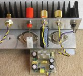
NO CAPS!...any cap, no Miller....and reduced to 22pf the input units, 10 pF the feedback line and 220 pf the feedback transistor base to emitter connection.
My rails condensers are 470uf each one... cable from PSU have 25 centimeters long only.... all condenser bypassed with 100N
From feedback line to ground; 39 ohms and 3300 uF
Bootstrap is using the correct value, and to positive line decoupling filter,in the input, was maintained the 220uf.
My zobel is using 2,2 ohms.
BC556C gain is 310
Voltage amplifier gain is 100
Driver gain is 85
New Sankens, 90 the NPN and 105 the PNP
It is fair to stop your research...but i do not believe that you will succeed in your plans...this is some vírus... "audiococus fidélitus"...will hold you again and again.
The sound quality is very special...will be hard to reproduce better sound that your unit and the others i mentioned in that thread...each one with their own characteristics.
I will be watching new ideas.... will be constructing Hugh designs, your designs... and keeping the interest for audio alive.
Well, in my mind, having not more questions appearing here, from our forum friends, i will let the thread die...going to archive, and disappearing from main page.
But if someone need something..i am here to help or try to.
nanabrother@yahoo.com
I am sorry, i received 8 mails asking for AKSA diagram...i cannot show the circuit secrets..this belongs to Hugh....the schematic i can offer, is this one.
http://www.diyaudio.com/forums/showthread.php?postid=415380#post415380
regards,
Carlos
Had not problems with the construction, voltages are normal, off set appear a little bit bigger than the last one...11 milivolts, but everything in order...was assemble and power was switched on without any surprise...current measured over protective resistor that were removed and substituted by rail fuses.
I was afraid of the bias adjustment trimpot, so i installed a 110 ohms resistor...and ready to go!
100 ohms trimpot is in the maximum...good current in the extra NPN, having something around 250mA....and 620 mA each rail.
It is producing more than 100 watts RMS over 4 ohms...but this is not important, as that difference is nothing to human hearing, as 10 or 20 percent increase is not perceived.
NO CAPS!...any cap, no Miller....and reduced to 22pf the input units, 10 pF the feedback line and 220 pf the feedback transistor base to emitter connection.
My rails condensers are 470uf each one... cable from PSU have 25 centimeters long only.... all condenser bypassed with 100N
From feedback line to ground; 39 ohms and 3300 uF
Bootstrap is using the correct value, and to positive line decoupling filter,in the input, was maintained the 220uf.
My zobel is using 2,2 ohms.
BC556C gain is 310
Voltage amplifier gain is 100
Driver gain is 85
New Sankens, 90 the NPN and 105 the PNP
It is fair to stop your research...but i do not believe that you will succeed in your plans...this is some vírus... "audiococus fidélitus"...will hold you again and again.
The sound quality is very special...will be hard to reproduce better sound that your unit and the others i mentioned in that thread...each one with their own characteristics.
I will be watching new ideas.... will be constructing Hugh designs, your designs... and keeping the interest for audio alive.
Well, in my mind, having not more questions appearing here, from our forum friends, i will let the thread die...going to archive, and disappearing from main page.
But if someone need something..i am here to help or try to.
nanabrother@yahoo.com
I am sorry, i received 8 mails asking for AKSA diagram...i cannot show the circuit secrets..this belongs to Hugh....the schematic i can offer, is this one.
http://www.diyaudio.com/forums/showthread.php?postid=415380#post415380
regards,
Carlos
Re: I am using small electrolitc condensers directly over the amplifier board.
Hi Carlos,
Sorry for not postings earlier but I seem to take to long to write my responses and it prevents me from posting. I've started using word so I have a copy resend again.
Thanks for the information on your PSU, it gives me some food for thought.
My schematics are just copied from my texts so I don't feel I need to be thanked.
I have just started to use a CAD package, and haven't actually produced a real PCB yet. So coming up with a GEM PCB isn't going to be happening soon.
You're method of producing PCBs work very well for you. You produce results every day. A much better philosophy than mine. Unfortunately, I'm one of those people that take forever to do anything, I think about everything. For example, in the GEM schematic I posted earlier, I moved the text around many times until it looked just right to my eye and that was just for the resistor symbol.
Thanks
destroyer X said:My PSU is inside a metal case, and many parallelled caps are inside.
In the reality Greg, there are two transformers, each one with their own full wave rectifier, and if i remember (do not know exactly) there are around 15000uF capacitance each rail.
I think you have the rigth to install your Condensers directly over the board, as suggested by Graham.
Thank you Greg, i will use your schematic, and i am sorry, the one i suggest was "with inverted logics"....was wrong, i am very sorry.
The 100 ohms trimpot, that you substitute with a 47 ohms trimpot, with a resistor in series, i think 50 ohms will complete the standard value, and can be installed in the place you put interrogation marks.
The clever resistor network you made, for the bias adjustment, will be better to have a result of 1K ohms when you add all resistors together....but will work also, as normally this network is calculated from 3 to 10 times the real base current..so, will work great!, and protected against mistakes that can produce enormous current.... depending on supply capacity...the 220 will be the main protector.
Greg, if you know how to make, having a good CAD tool to help you, please, make this board you are telling that will prefer to use..this one with power transistors installed over it...and publish that board here, will be a very good cooperation.
I know my boards are ugly and strange... i first created them when very young and doing the same now a days...my board was created in 1970...this was made to be simple, fast and to go checking while assembling...to use glue to fix boards, to avoid shorts...but it is not the kind of work people prefer, as the guys majority in this forum, are producing diy work but alike professional does...not as home made diy work, without more pretentions are beeing done here...so...having the chance to help us...please, go ahead and prepare a more professional board, that will be very well received by the community majority.
Hi Carlos,
Sorry for not postings earlier but I seem to take to long to write my responses and it prevents me from posting. I've started using word so I have a copy resend again.
Thanks for the information on your PSU, it gives me some food for thought.
My schematics are just copied from my texts so I don't feel I need to be thanked.
I have just started to use a CAD package, and haven't actually produced a real PCB yet. So coming up with a GEM PCB isn't going to be happening soon.
You're method of producing PCBs work very well for you. You produce results every day. A much better philosophy than mine. Unfortunately, I'm one of those people that take forever to do anything, I think about everything. For example, in the GEM schematic I posted earlier, I moved the text around many times until it looked just right to my eye and that was just for the resistor symbol.
Thanks
Graham Maynard said:Hi Greg,
Regarding your bias sketch.
I use a clear bodied 15 turn 1k and 50R Bournes Multi-turn cermet trimmers. The adjustment is very extended for the class-AB adjustment but a little more critical though still easy for the class-A biasing.
I have not used those little horseshoe shaped horrors for bias adjustment for some time, and thus it did not occur to me that I should mention anything.
Just use 15 (or 10) turn pots as they are; it much more simple.
I don't like mounting power transistors on a pcb and then bolting them to a heatsink.
After a working lifetime of bad words related to thoughtless designers who turn simple repairs into ten times the work stripping everything down, well, what more can I say; there's clever/smart and there's common sense ! Swopping wires or trying a completely different device type when the are heatsink mounted is just so easy.
I use Panasonic 10mF/63V and these are not too big for PCB mounting, but again I want an easy construction, so for me they are either side of pcb.
A fuse and wires from psu can have a resistance, and I don't want to risk more common mode distortion than necessary at any frequency. That is my reason for a big 'C' after the fuse. The psu with smoother capacitors is separate. For all I know this arrangement actually helps the amplifier to sound good, I have not check other ways.
Nor did I instruct Carlos on how to build his. I e-mailed him the circuit and the next I knew this thread arrived. His capacitor placings are similar to mine and he mounts power transistors on heatsinks; maybe the same thought processes, or practical, or just old fashioned.
Hello Graham,
(sorry for the delay, I'm having trouble posting)
I have always used Bournes Multi-turn cermet trimmers (or similar) and am not 100% sure what you are inferring to about the horseshoe shaped horrors. My thoughts and Carlos's was to have resistance in series to prevent an over bias situation if you accidentally set the pot to the wrong position. This will not a problem when you are experienced or careful. The other issue I have read about is the wiper of a pot is supposed to be a common point of failure. I never experienced it myself but apparently someone has and thought it necessary to document it.
I can appreciate you position on mounting transistors and you make a good point if you do a lot of experimenting with the output devices. Wires from the PCB to the output devices just don't seem to be an elegant solution to me. I know this is irrational as many excellent amps use this arrangement. A big advantage of your approach is the amp PCB becomes simpler to design.
I've been looking into sourcing 10,000uF 50V or 63V caps and the all seem to be close to 35mm in diameter. Any more clues?
I have often thought about using the resistance of the power wires and fuse to be the R in a CRC filter, which is pretty much what you indicate you have done with the first capacitor being on the PSU and the second cap being after the fuse on the amp PCB.
Thanks
Greg Erskine said:
I've been looking into sourcing 10,000uF 50V or 63V caps and the all seem to be close to 35mm in diameter. Any more clues?
Hi Greg,
there are a few 10000u caps with less than 35mm diameter. The one I'm going for is Panasonic TSUP series 50V 10000u 85C snap-in, ECOS1HP103CA. This has a 25mm diameter. It's stocked by RS components in the UK. Sorry, no idea of an Aussie supplier.
James
nemestra said:Hi Greg,
there are a few 10000u caps with less than 35mm diameter. The one I'm going for is Panasonic TSUP series 50V 10000u 85C snap-in, ECOS1HP103CA. This has a 25mm diameter. It's stocked by RS components in the UK. Sorry, no idea of an Aussie supplier.
James
Thanks James,
I was actually looking at RS components (Australia) online and have the catalogue and missed it both times (339-6887). It was right there infront of me, must be a trees/forest thing. Thanks again.
Hi Carlos,
I'm very pleased to hear that your GEM amplifier is going again.
Sure, we learn so much from our failures, they help us to move forwards !
And failures that are shared help everyone as much as the successes do.
You only have 250mA in the class-A, but you still should not have 650-250=400mA in the class-AB. Just go for 100mA class-AB.
I'm sure you always double check when hot; if I set for 500mA total when hot, the cold switch-on current is only 350mA, but the amplifier soon stabilises and still runs well the moment it is powered-up.
NO CAPS ! Excellent.
That means you have got rid of the stray capacitance you had before. Having tightly twisted wires running between pcb and the output stage transistors can do this, and I suspect the lack of basic stability you had before played a part in the failure when you increased the gain-bandwidth of the output stage devices by increasing the supply rail voltages. (You can always bridge for increased power.)
I note that some JLH class-A constructors twist the wires going to the output devices, but that is *not* correct; I also note that some JLH constructors complain of instability problems where there should not be any. I have made capacitors by twisting wires together in order to obtain some particular response at RF, but it is very hard to predict what the resultant value will be. Thus I wonder how amplifier constructors know what additional cross-couplings they are creating when they twist wires.
The stability without additional signal path capacitors is also most satisfying for me too, because it means that the circuit is properly repeatable, whilst for those who do experience a problem, you have already proved that a simple 47pF Miller capacitor at the VAS is an effective cure.
I wish you enjoyment in listening to your carnival music.
(I think I have a different strain of that virus Carlos, mine is an electronics variant, not just 'audiococus fidelitus'. Terrible, isn't it !)
Cheers .......... Graham.
Hi Greg,
Save a MS 'Wordpad' document to your Desktop.
Use this to write + save your posting in, and minimise to the taskbar.
(You can have different Wordpad messages for different threads.)
Then call up the Posting page and do a;
Edit/select all; right click/copy from Wordpad;
and right click/paste to the Posting page.
I would always make a lash-up of a circuit to see if it really was suitable before I took all the time and trouble of making a pcb for an unknown project.
Horseshoe horrors - those little open frame pre-sets where the contact resistance changes with time. The Bournes 15 turn pre-sets have their wiper sprung against an enclosed sliding block.
I know what you are implying about the risk of higher contact resistance and overbiasing, but driver current is only 40 to 50 mA and if the pot is first set to the half-way position using a multimeter (or visually with the clear bodied ones I use) then such worries are unfounded.
An alternative would be to replace the class-A bias pre-set with 22 ohms and then adjust the value of the 390 ohm resistor, but not with a simple pre-set because this component potentially swings through the full rail to rail output voltage, and this could lift dissipation up to circa 1.5W.
Wire capacitance. I have only one critical wire between my pcb and the heatsink, a short fine one between the mirror and the VAS.
All others are neatly hardwired on the heatsink.
Yes I suppose the fuse does make for a C-R-C filter.
I used 10mF beside pcb because a bootstrap at a the VAS does not theoretically have as good a common mode rejection ratio as a CCS and I wanted low rail impedance at low frequencies to be sure of clean reproduction.
I think my capacitors are TSUP series.
Warning; they will retain good charge for weeks, if not months.
Always discharge, or fit a bleeder in case of fuse failure.
Cheers .......... Graham.
Graham Maynard said:Hi Greg,
Save a MS 'Wordpad' document to your Desktop.
Use this to write + save your posting in, and minimise to the taskbar.
(You can have different Wordpad messages for different threads.)
Then call up the Posting page and do a;
Edit/select all; right click/copy from Wordpad;
and right click/paste to the Posting page.
I would always make a lash-up of a circuit to see if it really was suitable before I took all the time and trouble of making a pcb for an unknown project.
Horseshoe horrors - those little open frame pre-sets where the contact resistance changes with time. The Bournes 15 turn pre-sets have their wiper sprung against an enclosed sliding block.
I know what you are implying about the risk of higher contact resistance and overbiasing, but driver current is only 40 to 50 mA and if the pot is first set to the half-way position using a multimeter (or visually with the clear bodied ones I use) then such worries are unfounded.
An alternative would be to replace the class-A bias pre-set with 22 ohms and then adjust the value of the 390 ohm resistor, but not with a simple pre-set because this component potentially swings through the full rail to rail output voltage, and this could lift dissipation up to circa 1.5W.
Wire capacitance. I have only one critical wire between my pcb and the heatsink, a short fine one between the mirror and the VAS.
All others are neatly hardwired on the heatsink.
Yes I suppose the fuse does make for a C-R-C filter.
I used 10mF beside pcb because a bootstrap at a the VAS does not theoretically have as good a common mode rejection ratio as a CCS and I wanted low rail impedance at low frequencies to be sure of clean reproduction.
I think my capacitors are TSUP series.
Warning; they will retain good charge for weeks, if not months.
Always discharge, or fit a bleeder in case of fuse failure.
Cheers .......... Graham.
Hi Graham,
I often use notepad, wordpad, word or my favourite is editpad. I just do a [Crtl] A, [Ctrl] C then [Ctrl] V or drag and drop. It just depends on what machine I'm on and which icon is closest.
")
I haven't done any PCBs yet so I need the practice. Lashing up is still time consuming to me. See the attchment. I trust Carlos's judgement, if it comes close to an AKSA then I know it will be worthwhile.
I just measured the resistance of some 20mm fuses, they vary from 0.06 to 0.02 ohms for 1 to 5 amp fast blow fuses. I only have a few large size fuses but they gave high values of tenths of ohms or even a few ohms for 0.5 and 1 amp fast blow fuses. I must get a few more to test. I guess their resistance will change depending on current flow.
I don't know how significant the VAS bootstrap lower common mode rejection ratio is. It might be by chance that of my amps the ones I prefer have a bootstrap rather than CCS.
I just looked up the TSUP. 25mm diameter and AU$11. I've learnt the lesson of caps discharging back in my study days. I vapourised a piece of wire and scared the **** out of the whole class with the loud zap.
Thanks
Attachments
GEM Amplifier
Hi Graham,Carlos and Greg,
Please do not think that lack of postings equates to lack of interest.....!
The very interesting and entertaining (!) threadhas spurred me to start CADing up the circuit last night. All being well a PCB for the GEM will follow soon.
Unfortunately I am not as fast as Carlos
Thanks to all
Barry
Barryblue, not so fast, but certainly will make things better and more pretty related
the awfull things i do.
Everything is a compromisse...faster will be ugly, slowly will be perfect.
We will wait your work, will be great.
Greg is also producing beautifull art work.
I am hearing rigth now!... the amplifier, it is nice to observe the details... well, it is running all day long.
I increased the current a little...gone to 800 miliamps and 300 miliamps to NPN extra transistor.... interesting sound...very clear.
But we cannot overdrive it...clip as a monster!..... the clipping sound is terrible.
But this third amplifier is a little different related the others i made, the first and second had different clipping...had to measure again to see if some Vbe is too much advanced that can result in easy saturation voltage.
It is sounding great....bass flows natural, with strengh, with impact, as a punch in our stomach...and we can perceive hi harmonics, related to fingers passing into guitar... the scratching over steel....nice that!
I am using a computer supply fan.... using 12 volts....noise is not heard, as amplifier is always playing loud, to be out of the main class A bias....amplifier is cold with the fan blowing air.
regards,
Carlos
Graham and Greg, very good to read your post... enjoyment to me.
I feel very good to see people sharing ideas this way.
I love this forum.
I twisted the wires again...ahahaha!..had to use caps to avoid oscilation.
You are more than rigth... twisted wires can produce 1 picofarad each inch, depending the wire insulation thickness.
Without twisted wires...no problem at all.
I removed the 2SC1819 transistor, and using another hi Speed unit..but this one was published as audio transistor.
Output with Sankens.
I increased the current...having fun with 800 miliamps more 300 miliamps for extra NPN..... will invert that situation near future... increasing extra NPN current and reducing AB units to 100 or a little bit more current.
Please Graham, check your mail, as i send you some images with information written over.
Greg is preparing pretty board....hummm, this thread will be very interesting, good people cooperating, will produce interesting images, very helpfull for the ones that intend to produce...i am hearing mine... since 6 hours early morning...it is cold..the computer fan is removing all heat....really temperature is around 33 degrees over transistors.
This amplifier has a very sensitive "Oscilator meter"...need only to touch the 47N or 2,2 ohms zobel...making foolishes related construction...just touch it and it will tell you that something is wrong.
regards,
Carlos
![graham[2]..jpg](/community/data/attachments/53/53352-492bde010298f421f07d53098de200e3.jpg)
Uoooops!...sorry, terrible accident, i made the mess...the image is from Graham.
Well, the image already gone....already done..... hehe.... what can i do...ahahaha.
But, take a look!
Don't you think he is nice?
He seems those genius Disney is producing...see the clever and kind eyes expression.
This is our friend Graham..... seems to be big daddy.
Hugh Dean is handsome too...he is a 190 centimeters nice giant!
regards,
Carlos
Attachments

Hi J.
It turns the differential pair into a single ended input at high frequency where the phase change would normally render the circuit unstable.
Hi Barryblue,
Look forwards to seeing your CAD results.
Hi Carlos,
Interesting comment about twisting wires.
I used to get about 10pF / inch with enamelled copper wire.
Cheers ......... Graham.
Carlos, no offense, just tying loose ends
Bias is not the only way to eliminate distortion in an amplifier, as this link will clearly show.
mastertech said:stokeri dont understand how is it possible to have a low distortion
from a class-b since there's no bias, how did he do it
can you provide a link of the schematic of this amplifier
in the meantime ill try googling to see if i can find anything
thanks for your help
cheers
Bias is not the only way to eliminate distortion in an amplifier, as this link will clearly show.
Hi J,
I answered your question yesterday and saw it posted but it has disappeared ?
The 10nF turns the input differential into a single input transistor at RF where the overall amplifier phase change would otherwise render the amplifier unstable.
Hi All,
Suppose I published plans for a kit car with several desirable features and I said that the front would not oscillate up and down when the throttle was repeatedly pressed and released because it is based on a rear wheel drive chassis.
Then somenone says it was built on a front wheel drive chassis and yeah it is a great car but the front still has up-down oscillation traits !!!
___________________________________________
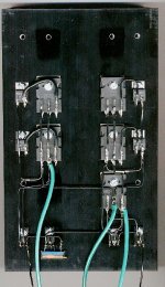
I have pulled the prototype heatsink off my amplifier and scanned it to show how neat and easy it can be for all those who ensist upon risking oscillation by mounting anything after the first four transistors on the pcb, or running all wires back to the pcb.
Note that I have a 22 ohm resistor where the class-A bias pot should be. This turned out to be exactly the correct value with my transistor, the 390/820 ohm VAS collector resistors, and the +/-36V rails, so it was substituted.
My wires and solder joints are still not what I would make for a finished product (this heatsink has carried many protypes and my iron was too cold).
Note that I use thick film emitter resistors, whilst back on the pcb I use old non-inductive 4x 10 ohm carbons for the Zobel.
The thin bottom left wire goes to the bootstrapped supply, and the thin bottom right wire is from the input stage, both on the pcb but separated from input transistors by the additional supply rail filter capacitors.
The thick wires go back to pcb as L=+ve; C=output; R=-ve.
The power transistors are 2x NPN to the left and 2x PNP plus lower NPN to the right.
This is so much easier to construct, and will be easier for me to modify, or repair in the event of failure.
Why complicate when the most basic option is the best ?
Uncle Graham advises you that your circuit might oscillate if constructed differently to the manner already specified, and if it does you will need to experiment by fitting Miller 'C' etc.
Cheers .............. Graham.
I answered your question yesterday and saw it posted but it has disappeared ?
The 10nF turns the input differential into a single input transistor at RF where the overall amplifier phase change would otherwise render the amplifier unstable.
Hi All,
Suppose I published plans for a kit car with several desirable features and I said that the front would not oscillate up and down when the throttle was repeatedly pressed and released because it is based on a rear wheel drive chassis.
Then somenone says it was built on a front wheel drive chassis and yeah it is a great car but the front still has up-down oscillation traits !!!
___________________________________________
I have pulled the prototype heatsink off my amplifier and scanned it to show how neat and easy it can be for all those who ensist upon risking oscillation by mounting anything after the first four transistors on the pcb, or running all wires back to the pcb.
Note that I have a 22 ohm resistor where the class-A bias pot should be. This turned out to be exactly the correct value with my transistor, the 390/820 ohm VAS collector resistors, and the +/-36V rails, so it was substituted.
My wires and solder joints are still not what I would make for a finished product (this heatsink has carried many protypes and my iron was too cold).
Note that I use thick film emitter resistors, whilst back on the pcb I use old non-inductive 4x 10 ohm carbons for the Zobel.
The thin bottom left wire goes to the bootstrapped supply, and the thin bottom right wire is from the input stage, both on the pcb but separated from input transistors by the additional supply rail filter capacitors.
The thick wires go back to pcb as L=+ve; C=output; R=-ve.
The power transistors are 2x NPN to the left and 2x PNP plus lower NPN to the right.
This is so much easier to construct, and will be easier for me to modify, or repair in the event of failure.
Why complicate when the most basic option is the best ?
Uncle Graham advises you that your circuit might oscillate if constructed differently to the manner already specified, and if it does you will need to experiment by fitting Miller 'C' etc.
Cheers .............. Graham.
Attachments
Hi Graham,
Thank you for responding. It does almost turn it into a current feedback amp at some frequency that I suspect is not all that high. I think what bothers me about it is that it looks like: a lot too late. Though it sounds as though you have it tamed down there are still some bursts under certain conditions that you've mentioned and it occurs to me that it's the transconductance stage that's getting in the soup. Is there no way to compensate this second stage without incurring first cycle distortion?
Thank you for sharing your insights and the thought provoking articles you've written. The amp is obviously musical too. I just worry about it being able to play into anything.
J.
- Status
- This old topic is closed. If you want to reopen this topic, contact a moderator using the "Report Post" button.
- Home
- Amplifiers
- Solid State
- Incredible quality amplifier by Graham, prepare your ears for it