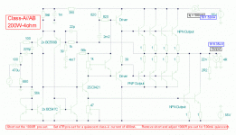
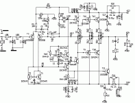
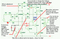
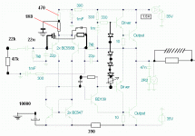
I have not assembled all those ones...but the ones i made sounded great.
Sounds alike JLH...having more bass...more dinamics...more power.
Good...very good amplifiers.
All them need adjustment in biasing and some resistors to match the units you will use.
regards,
Carlos
Sounds alike JLH...having more bass...more dinamics...more power.
Good...very good amplifiers.
All them need adjustment in biasing and some resistors to match the units you will use.
regards,
Carlos
Attachments
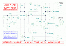
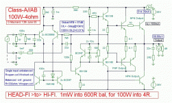
Any of those amplifiers are supplied as kit form, they are not comercial units
And some of them need to tweak the emitter resistor, in the differencial, to adjust off set voltage.
Also some of them will need you to change value of the first transistor colector resistor to bias adequatelly the voltage amplifier stage...and so on.
To assemble and ready...if not human error...go to Symassym or some other kit form.
Those ones, unfortunattelly are "in adjustment" designs, as theya are flexible related components, supply voltage and more things...and all those things turns the amplifier something that will provide you the fun to adjust them.
regards,
Carlos
Yes Diego, i think it will work fine.
Good luck.
Precisando de alguma coisa pode dispôr.
Needing some help, please, come to me...Using our forum or even directly.
nanabrother@yahoo.com
regards,
Carlos
Good luck.
Precisando de alguma coisa pode dispôr.
Needing some help, please, come to me...Using our forum or even directly.
nanabrother@yahoo.com
regards,
Carlos
I am feeling good to met you again Ed...also happy that i could be usefull
I love to explain those obvious things that people normally do not explain...i suppose they imagine that everybody already knows...because those things i use to explain are very basic ..a simple knowledge that the majority believe everyone knows.
But there's always people that do not know something, and those may be shy to ask...this way i can be helpfull to those ones.
I love to contribute....people satisfaction is my target, and this constitute the best prize i can have.
Many young guys are constructing and some of them already finished GEM...this is very good ...i feel good with that.
Thank you.....you have made my day.
regards,
Carlos
Carlos, a simple question.
As everybody can see, Graham really like low input impedance so we need to use a really large input cap and we need to go for eletrolytics.
Maybe a higher input impedance and a low value polypropilene cap would be better?
Have you made this test?
regards.
ps.: Carlos, someday I will build a GEM too, and you are guilt for that.
Diego,
I like to use large input cap, this is more better than small value caps.
In here, I'm using on my gainclone, a 68uf made by Siemens.
Why do you like to use so many output transistors on a amplifier with 30w?
You can use only 2sc5200 and a 2sa1943! You isn't need more than ONE PAIR!
Best Regards,
Felipe Navarro
hi everybody....
low input impedance... dun stress the preamplifier.... is a good choise....
well...
my GEM amplifier... is finally working....
this amplifier has a nice structure... easy to project the pcb...
but has a lot of oscillation... n may burn some transistors... cause this take care... use caps.. and zobel to try eliminate this oscillation....
now.... i have to project the IR receiver... to control Volume n Mute... just a PIC...
the GEM has a nice deep bass... and its so linear... great velocity...
great dynamic.... ill test more n more... hehehehehe
now im using the old toshibas transistors... the 2SC3281 and 2SA1943... they are originals.... maybe... next year... i change some output transistors... newer n better....
cya
Felipe, I don't know here do you read that I want to use a lot of transistors. I'm going to use only one pair of NPN devices for each channel. Thats why I liked that old schematic.
About the caps, finding a good caps with a reasonable value it's hard in Brazil and expensive. A higher input impedance and a lower value cap will do the same results in theory. That's why I asked Carlos if in pratice the result is different for this specific circuit.
Regards.
About the caps, finding a good caps with a reasonable value it's hard in Brazil and expensive. A higher input impedance and a lower value cap will do the same results in theory. That's why I asked Carlos if in pratice the result is different for this specific circuit.
Regards.
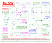
Graham made the amplifier customised to his own needs.
Also he perceived, despite Vinyl analogic recordings are his preference, that a lot of guys use CD players, MP3 players, Ipods and things alike as signal source.
Also that some good pre amplifiers have a very low output impedance, that is adequated to transfer signal into low and high impedance power units.
Because of that, answering his own needs...seasonal needs, he made the amplifier with low input impedance.... some of them have load resistors in the output, to help the matching with the CD player low impedance output amplifier...... so...using the low impedance, low power output, as a pré amplifier....as a signal source.
Of course you can change this.....better than re-calculate the whole thing, is to remove the load resistor that we have in the input.... from the input to ground...representing a load to the signal source amplifier....with this remotion, and, the increase of the input series resistor,you will "create", a more confortable sittuation to the standard hi impedance source.........better than that is to install an adequate resistor, from input to ground, to create a fake impedance that will make the pre amplifier work happy...and to avoid the first stage impedance to load the pré amplifier....than install a series resistor using big resistance value...at least half the signal source impedance.
Siganl level can be adjusted in the feedback line....the resistor you have in series between the output line and the differencial feedback resistor, can be changed to increase ...or decrease, the gain..this will make the amplifier more sensitive or less sensitive related the standard of 750 milivolts to start saturation (others use 1 Volt RMS...and many others use to decide for other choices..depends from the designer intentions).
It is good that Mod_evil is using his knowledge with the intention to help...this is very positive..... as we have learned, because people had good intentions, because they lost time with us, having patience with us too.
Alike every amplifier, you can tweak this one...... at your will.... you can include rail series resistors...very low values as Michael Bittner prefer to use, not to created sacrifices in driver signal levels...or you can reduce your output power to have room to use weaker supplies that will variate the voltage at the input differential...your choice.
My choice normally is 180 ohms....of course, depending the current drained in the input stages.
So, this will increase, a little, the stability when you face the supply voltage decrease, when the amplifier was severily driven...insulating the input from the output stages voltage variations.
Also you can reduce the bootstrapp electrolitic condenser....also you can install 100n capacitors in parallell with all electrolitic condenser...also you can install electrolitic condenser in a polarity arrangement that will turn the pair something alike a non polarized unit.
Your idea to modify the input's impedance will be nice to reduce the input capacitor value...as the value needed, after modifications, will be many times smaller.
You can install....or change the suck out capacitors values..... you can install or change value of stop resistors.
To increase stability you can install a big capacitor...a 103 unit from base to emitter...in the feedback line transistor.... the one connected into the output line..... with it's base pointed to the output side.
Eva already told that a capacitor in series with a resistor will produce better results than a single capacitor when we think to install a Miller capacitor...... in the voltage amplifier....from base to colector.
Also an arrangement, in the differential..... resistor in series with a capacitor...lets say...220 ohms and 100 picofarads (Eva will explain how to calculate...i do not know how to do it).... this arrangement can be installed from input base to feedback base....both transistors in the differential pair.
Of course....you can replace the bias trimpot, using diodes... 4 diodes and an adjustable series resistor will produce a good work too...having the advantage that diodes will reduce its voltage when heated by the heatsink.... producing some control over the stand by current when the amplifier turn too much hot...Diodes, in this case must be mechanically coupled into the heatsink..using thermicall grease compound and mechanicall arms to fix them and rubber schrimk tubes to insulate them from the heatsink to avoid shorts.
The differential emitter resistor can be splitted in two....and a capacitor can be installed in the middle..... one extreme to ground...to increase stability and filtering.
Well...there are hundreds of modifications that can be done...and many will create different sonics...this amplifier can be tuned.
One of the best amplifiers i could listen was a tuned Aksa, a Nirvana 55 to be more specific...that one had a very modified bootstrapped circuit...and the sonics differences are very clear...so..... those things can be customised to your personal taste.... adequating to your music, speakers used and acoustic environment.
You can do whatever you want...respecting that output line must be at zero volts potential related to ground...input and feedback differential transistor bases must be near the zero volt related to ground (measured from base to ground)...all transistor must measure more than 550 milivolts from base to emitter....the voltage amplifier must measure more than 550 milivolts...maybe 600 or 640 milivolts from base to emitter.....achieve this...the amplifer will work....beeing carefull, not to drain enormous current in the stand by mode...having a good voltage into the amplifier, to provide an output swing.... also this care will be needed...as you can adjust 5 amperes to stand by current...and the supply voltage can fall down to a very low value...and this will be very bad to sonics and general transistor biasing...so...errors must be enormous to stop the unit to oscilate following input audio signal (amplification)
regards,
Carlos
Re: Graham made the amplifier customised to his own needs.
Another addition to the English language dictionary.
First we had Explendid:
Excellent, adjective - of great virtue or high quality + Splendid, adj. - magnificent, inspiring = Explended adj. - of such great virtue as to be inspiring.
And now we have Adequating (also the verb Adequate, and the past tense, Adequated):
Adequate, adj. - equal to certian requirement or occasion.
Adequate, verb - the process of transforming an object to meet a certian requirement.
You are going to keep Webster busy.
I like these new words.
Sheldon
destroyer X said:adequating to your music, speakers used and acoustic environment.
Carlos
Another addition to the English language dictionary.
First we had Explendid:
Excellent, adjective - of great virtue or high quality + Splendid, adj. - magnificent, inspiring = Explended adj. - of such great virtue as to be inspiring.
And now we have Adequating (also the verb Adequate, and the past tense, Adequated):
Adequate, adj. - equal to certian requirement or occasion.
Adequate, verb - the process of transforming an object to meet a certian requirement.
You are going to keep Webster busy.
I like these new words.
Sheldon
- Status
- This old topic is closed. If you want to reopen this topic, contact a moderator using the "Report Post" button.
- Home
- Amplifiers
- Solid State
- Incredible quality amplifier by Graham, prepare your ears for it
![gem[1].wmf.gif](/community/data/attachments/66/66530-52721398521afe35cf93404d5dc71b05.jpg)
