Hi Jenyok, what was the problem with the models. Most of them are current limited and if you push them past their current limit they behave strangely. The current limit of almost all of the models is I believe 0.5A
I used the discrete model from TI and changed the params of the QP and QL transistors to get a more accurate reference voltage as follows:
.MODEL QNL NPN(EG=1.22 BF=80 RB=100 CCS=1.5PF TF=.3NS TR=6NS CJE=2PF
+ CJC=1PF VAF=100 IS=6E-13 NF=1.1623)
.MODEL QPL PNP(BF=40 RB=20 TF=.6NS TR=10NS CJE=1.5PF CJC=1PF VAF=50 IS=6E-13 NF=1.1623)
Note I don't remember how I worked out that those were the things I should change, I may have known what I was doing at the time though I probably didn't..... the end result was an improvement in the accuracy of the reference voltage though as far as I can recall.
whole model is as follows:
Note that this model still has the 0.5A limitation.
Tony.
I used the discrete model from TI and changed the params of the QP and QL transistors to get a more accurate reference voltage as follows:
.MODEL QNL NPN(EG=1.22 BF=80 RB=100 CCS=1.5PF TF=.3NS TR=6NS CJE=2PF
+ CJC=1PF VAF=100 IS=6E-13 NF=1.1623)
.MODEL QPL PNP(BF=40 RB=20 TF=.6NS TR=10NS CJE=1.5PF CJC=1PF VAF=50 IS=6E-13 NF=1.1623)
Note I don't remember how I worked out that those were the things I should change, I may have known what I was doing at the time though I probably didn't..... the end result was an improvement in the accuracy of the reference voltage though as far as I can recall.
whole model is as follows:
*LM317 TI voltage regulator - pin order: In, Adj, Out
*TI adjustable voltage regulator pkg:TO-3
.SUBCKT LM317D 1 2 3 **Changes my be required on this line**
J1 1 3 4 JN
Q2 5 5 6 QPL .1
Q3 5 8 9 QNL .2
Q4 8 5 7 QPL .1
Q5 81 8 3 QNL .2
Q6 3 81 10 QPL .2
Q7 12 81 13 QNL .2
Q8 10 5 11 QPL .2
Q9 14 12 10 QPL .2
Q10 16 5 17 QPL .2
Q11 16 14 15 QNL .2
Q12 3 20 16 QPL .2
Q13 1 19 20 QNL .2
Q14 19 5 18 QPL .2
Q15 3 21 19 QPL .2
Q16 21 22 16 QPL .2
Q17 21 3 24 QNL .2
Q18 22 22 16 QPL .2
Q19 22 3 241 QNL 2
Q20 3 25 16 QPL .2
Q21 25 26 3 QNL .2
Q22A 35 35 1 QPL 2
Q22B 16 35 1 QPL 2
Q23 35 16 30 QNL 2
Q24A 27 40 29 QNL .2
Q24B 27 40 28 QNL .2
Q25 1 31 41 QNL 5
Q26 1 41 32 QNL 50
D1 3 4 DZ
D2 33 1 DZ
D3 29 34 DZ
R1 1 6 310
R2 1 7 310
R3 1 11 190
R4 1 17 82
R5 1 18 5.6K
R6 4 8 100K
R7 8 81 130
R8 10 12 12.4K
R9 9 3 180
R10 13 3 4.1K
R11 14 3 5.8K
R12 15 3 72
R13 20 3 5.1K
R14 2 24 12K
R15 24 241 2.4K
R16 16 25 6.7K
R17 16 40 12K
R18 30 41 130
R19 16 31 370
R20 26 27 13K
R21 27 40 400
R22 3 41 160
R23 33 34 18K
R24 28 29 160
R25 28 32 3
R26 32 3 .1
C1 21 3 30PF
C2 21 2 30PF
C3 25 26 5PF
CBS1 5 3 2PF
CBS2 35 3 1PF
CBS3 22 3 1PF
.MODEL JN NJF(BETA=1E-4 VTO=-7)
.MODEL DZ D(BV=6.3)
.MODEL QNL NPN(EG=1.22 BF=80 RB=100 CCS=1.5PF TF=.3NS TR=6NS CJE=2PF
+ CJC=1PF VAF=100 IS=6E-13 NF=1.1623)
.MODEL QPL PNP(BF=40 RB=20 TF=.6NS TR=10NS CJE=1.5PF CJC=1PF VAF=50 IS=6E-13 NF=1.1623)
.ENDS LM317 **changes may be required on this line**
Note that this model still has the 0.5A limitation.
Tony.
Need a good model of LM317 for simulation program LTSpice IV, all known models in internet work bad.
I tested 17 different models of LM317 in LTSpice IV and the results were bad and very bad for models.
When simulating the LM317 you have to remember that the voltage is referenced between Vout and Adjust. (i.e. not ground)
Put a 1 ohm resistor between the voltage divider and the adjust pin and drive 1mA across this resistor. Gives you 1mV of perturbation voltage.
I tested various models of LM317 (18 different models), founded in internet.
Results are in atteched files ZIP.
Output voltage must be ~= 15 Volts for R1 = 5.17 kOhm R2 = 470 Ohm .
Load current is 0 ... 0.7 (0.6) A step 10 mA .
More realistic model is LM317-TEST1 .
LIB and ASY files must be placed in "C:\PROGRAM FILES\LTC\LTSPICEIV\LIB\SYM\EXTRA\VOLREG" .
LM317_2.ZIP ... LM317_6.ZIP are ZIP files with JPG pictures of testing results.
.
I think that results are bad and very bad for all models of LM317 .
Attachments
Last edited:
Hi Jenyok. I assume that you're not happy with the output voltage dropping with increasing current? Have you done any real world tests to ensure that this is not something that happens with a real LM317?
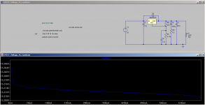
I ran a sim on the model I had and the results seem well within spec for an LM317
15.27566V @20mA
15.27147 @ 500mA
actual difference = 0.00419
0.3% of 15V = 0.045V (load regulation is specified as max 0.3%)
Picture attached. Or have I missed something?")
Tony.
I ran a sim on the model I had and the results seem well within spec for an LM317
15.27566V @20mA
15.27147 @ 500mA
actual difference = 0.00419
0.3% of 15V = 0.045V (load regulation is specified as max 0.3%)
Picture attached. Or have I missed something?
Tony.
Attachments
wintermute
.
Yes, simple tests are of the output voltage dropping with increasing current from 0 ... 0.7 A .
.
Value 0.3% and 0.00419 Volt or 4.19 mVolts seems to me, that LM317 is a very bad as a voltage regulator (stabilizator).
.
I am very unsuccessfull that current value from 0 ... 20 mA gives about 10 mVolts dropping of output voltage. I don't understand, why ?
.
Yes, simple tests are of the output voltage dropping with increasing current from 0 ... 0.7 A .
.
Value 0.3% and 0.00419 Volt or 4.19 mVolts seems to me, that LM317 is a very bad as a voltage regulator (stabilizator).
.
I am very unsuccessfull that current value from 0 ... 20 mA gives about 10 mVolts dropping of output voltage. I don't understand, why ?
Last edited:
You have to pull *at least* 10mA according to the datasheet for the regulation figures to be accurate. No regulator I know of gives +/- 0mV at zero current draw. You can avoid this by ensuring a 10-20mA minimum current pull (e.g.load suitable resistor permanently accross the output) or maybe your circuit already draws this minimum amount; in which case you don't have cause for concern. Beleive me, I've done all sorts of discrete regulator circuits; it's one of the first things you learn when building them in PRACTICE.
wintermute
.
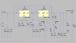
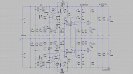
Try to simulate our Russian circuit of power reg, see results of simulation and compare results with LM317 as a power reg.
Output voltage ~= + - 15 Volts .
Output load current ~= 0 ... 1 A .
ASC file of circuit for LTSpice IV is in ZIP file.
.
Try to simulate our Russian circuit of power reg, see results of simulation and compare results with LM317 as a power reg.
Output voltage ~= + - 15 Volts .
Output load current ~= 0 ... 1 A .
ASC file of circuit for LTSpice IV is in ZIP file.
Attachments
Pay your attention to Texas Instruments products
.
TPS7A3001 Vin = -3 ... -36 V , Iout = 200 mA
TPS7A4901 Vin = 3 ... 36 V , Iout = 150 mA
.
TPS7A3301 Vin = -3 ... -36 V , Iout = 1 A
TPS7A4700 Vin = 3 ... 36 V , Iout = 1 A
.
as improvment and changeover to LM317, LM337 .
.
http://www.ti.com/product/tps7a4700?DCMP=analog_power_mr&HQS=tps7a4700-pr-in
http://www.ti.com/product/tps7a4901
.
TPS7A3001 Vin = -3 ... -36 V , Iout = 200 mA
TPS7A4901 Vin = 3 ... 36 V , Iout = 150 mA
.
TPS7A3301 Vin = -3 ... -36 V , Iout = 1 A
TPS7A4700 Vin = 3 ... 36 V , Iout = 1 A
.
as improvment and changeover to LM317, LM337 .
.
http://www.ti.com/product/tps7a4700?DCMP=analog_power_mr&HQS=tps7a4700-pr-in
http://www.ti.com/product/tps7a4901
Last edited:
Zobel network at LM317 output
I have noticed that Morgan Jones uses a 2R7 resistor in series with a 1uf capacitor at the output of the LM317 circuit. Is it there to prevent possible ringing or oscillations? Are LM317's notorious for such incidents?
By the way, I have built a simple guitar preamp using 30V regulated with the aid of a LM317 circuit. But when turning on the amp, there is a high frequency audible noise (close to 20kHz - maybe 15kHz? - I don't know) for 1 or 2 seconds, and then normal conditions - just like charging noise of electric weapons. I have noticed that it happens when the electrolytics have been completely discharged. When turning off and on again quickly, no such sound can be heard.
Is it possible that this is a momentary oscillation? The sound is like a pure sine wave. I am using two 100k resistors at the output to cut the 30V in half, putting a 220uf cap in the 15V joint. And of course this cap charges slowly, could it be the cuplrit of the transient?
Thank you for any input!
I have noticed that Morgan Jones uses a 2R7 resistor in series with a 1uf capacitor at the output of the LM317 circuit. Is it there to prevent possible ringing or oscillations? Are LM317's notorious for such incidents?
By the way, I have built a simple guitar preamp using 30V regulated with the aid of a LM317 circuit. But when turning on the amp, there is a high frequency audible noise (close to 20kHz - maybe 15kHz? - I don't know) for 1 or 2 seconds, and then normal conditions - just like charging noise of electric weapons
. I have noticed that it happens when the electrolytics have been completely discharged. When turning off and on again quickly, no such sound can be heard.Is it possible that this is a momentary oscillation? The sound is like a pure sine wave. I am using two 100k resistors at the output to cut the 30V in half, putting a 220uf cap in the 15V joint. And of course this cap charges slowly, could it be the cuplrit of the transient?
Thank you for any input!
Yes the resistor in series with the cap on the output is to suppress a resonance that occurs due to the output inductance of the regulator forming a tuned circuit with the output capacitor (normally only an issue if you use low esr capacitors of fairly large value).
2.7 ohms seems a little on the high side (I used 0.33 ohms on mine, which was right on the edge in the simulation).
Jenyok, I didn't see your subsequent posts. My levels of knowlege are relatively low it would take me a while to analyse these new circuits (and I still might not understand what they are doing )
Tony.
2.7 ohms seems a little on the high side (I used 0.33 ohms on mine, which was right on the edge in the simulation).
Jenyok, I didn't see your subsequent posts. My levels of knowlege are relatively low it would take me a while to analyse these new circuits (and I still might not understand what they are doing
) Tony.
Yes the resistor in series with the cap on the output is to suppress a resonance that occurs due to the output inductance of the regulator forming a tuned circuit with the output capacitor (normally only an issue if you use low esr capacitors of fairly large value).
2.7 ohms seems a little on the high side (I used 0.33 ohms on mine, which was right on the edge in the simulation).
I am using Nippon 22uf (63V, KMG series) - I don't know if these have such low ESR, but I don't know if this is the problem. I can experiment using an additional resistor and tantalum cap. Thanks for the answer!
Any tips on the weird charging noise? Could it be the resonance you mention?
Last edited:
Not really, here's a handy graph:
Using 3-pin regulators off-piste: part 3
NB the effective synthetic inductance of the output does depend slightly with the current drawn from the 317, dropping a lot from 5 to 50mA output - with pretty negligible change much beyond that point.
Using 3-pin regulators off-piste: part 3
NB the effective synthetic inductance of the output does depend slightly with the current drawn from the 317, dropping a lot from 5 to 50mA output - with pretty negligible change much beyond that point.
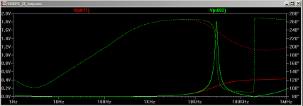
Thanks Martin! I suspect that the inductance in the model I have for the LM317 doesn't reflect reality I just simmed with 22uF cap (with no esr to get a really obvious peak) and the resonant peak was at 29Khz..
Attached pic to give an idea, red curve is with 0.5ohms in series with the 22uF cap
I just simmed with 22uF cap (with no esr to get a really obvious peak) and the resonant peak was at 29Khz.. Attached pic to give an idea, red curve is with 0.5ohms in series with the 22uF cap
Attachments
Tony
Have you taken into account the fact that the o/p inductance of the LM317 reduces significantly as Iout increases? I think Erol Dietz's measurements of resonant frequencies were for a datasheet implementation of the LM317 circuit with 5mA or 10mA Iout, but doesn't your circuit have a larger Iout and therefore a lower o/p inductance?
Have you taken into account the fact that the o/p inductance of the LM317 reduces significantly as Iout increases? I think Erol Dietz's measurements of resonant frequencies were for a datasheet implementation of the LM317 circuit with 5mA or 10mA Iout, but doesn't your circuit have a larger Iout and therefore a lower o/p inductance?
Last edited:
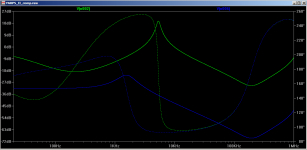
Hi Gopher, I tried the sim with low current, as you are correct the sim I posted above was using a 1A current source. I ran it at 10ma and there was virtually no difference.
However, I then realised that I was using my YARPS config (which is an implementation of Fred's 1 transistor upgrade earlier in this thread) and when I ran with a standard implementation the resonance peak indeed comes down
Blue is with 10ma load and yellow is with 1A load.
The version with the transistor shifts the resonant frequency up by quite a margin and also has very little difference between minimal and higher current.
Tony.
Attachments
- Home
- Amplifiers
- Power Supplies
- Improving the LM3x7 regulator circuit